Ion beam extractor

a technology of ion beams and extractors, which is applied in the direction of beam deviation/focusing, instruments, and beams by electric/magnetic means, etc., can solve the problems of difficult control of the direction of the ion beams, and the angle of the ion source b>1/b> must be changed, so as to achieve high ion flux and increase the ion beam extraction area

Inactive Publication Date: 2007-10-23
SAMSUNG ELECTRONICS CO LTD
View PDF6 Cites 14 Cited by
  • Summary
  • Abstract
  • Description
  • Claims
  • Application Information

AI Technical Summary

Benefits of technology

[0015]The present general inventive concept provides an ion beam extractor to extract a rectangular ion beam using a grid having slits formed therein, thereby increasing an ion beam extraction area and producing a high ion flux.
[0017]The present general inventive concept also provides the ion beam extractor to control the direction of the ion beam by application of the voltage thereto, thereby allowing application of the ion beam extractor to various processes without modification of hardware components.
[0018]The present general inventive concept also provides the ion beam extractor to control the direction and an intensity of the ion beam, thereby securing uniformity of a film while enhancing uniformity of an etching rate of a wafer, thereby increasing productivity of semiconductor diodes.

Problems solved by technology

When increasing the density of the plasma, there is a problem in that a direction of the ion beams is difficult to control by adjusting the electric field due to the fact that the neutral beam chamber typically comprises two or three electrodes in the grid 3.
Additionally, since the wafer 9 is rotated to enhance the uniformity of the etching rate, there is a problem in that an angle of the ion source 1 must be changed in order to change an angle of the ion beams.

Method used


Image

  • Ion beam extractor
  • Ion beam extractor
  • Ion beam extractor

Examples


Embodiment Construction

[0042]Reference will now be made in detail to the embodiments of the present general inventive concept, examples of which are illustrated in the accompanying drawings. The embodiments are described below to explain the present general inventive concept by referring to the figures.

[0043]FIG. 3 is a schematic structural view illustrating a neutral beam chamber according to an embodiment of the present general inventive concept.

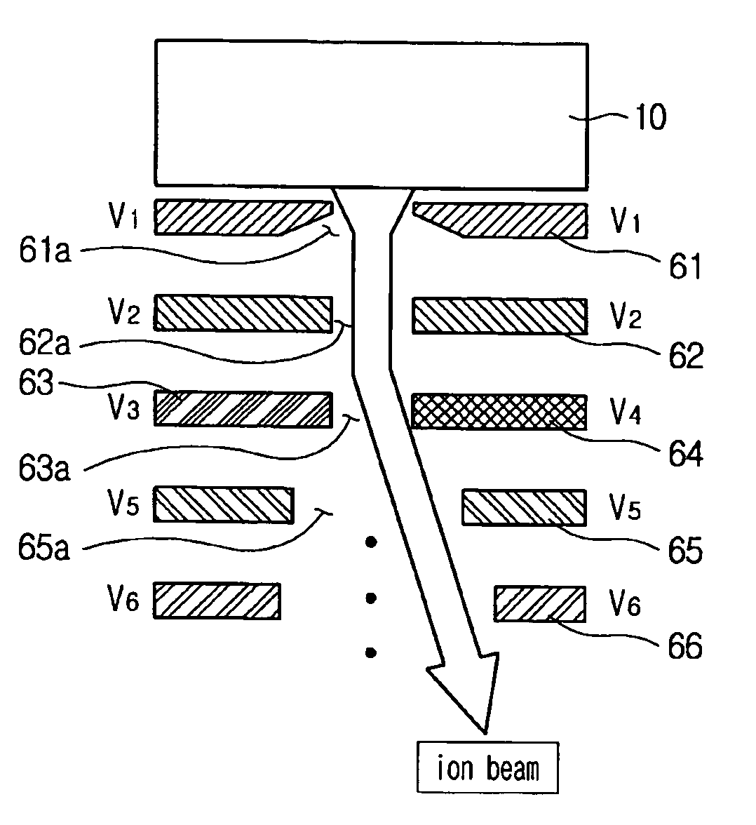
[0044]Referring to FIG. 3, the neutral beam chamber includes an ion source 10 to produce ion beams, a grid 20 located at a rear end of the ion source 10, a reflector 30 located at a rear end of the grid 20, and a wafer 40 located at a rear end of the reflector 30. After the ion beams produced by the ion source 10 pass through a plurality of slits 20a (FIG. 4) formed in the grid 20, the ion beams are reflected by the reflector 30 and are transformed into neutral beams. The neutral beams are then incident on the wafer 40 to etch an object film on the wafer 40.

[004...


PUM


Abstract

An ion beam extractor controls a direction and an intensity of ion beams by adjusting a voltage applied to a grid having slits formed therein, thereby enhancing uniformity of an etching rate of a wafer, leading to an increase of productivity of semiconductor diodes. The ion beam extractor comprises an ion source to produce an ion beam and at least one grid located at a rear end of the ion source in a progressing path of the ion beam produced by the ion source to adjust a direction of the ion beam by controlling a voltage applied to the at least one grid.

Description

CROSS-REFERENCE TO RELATED APPLICATIONS[0001]This application claims the benefit of Korean Patent Application No. 2005-1719, filed on Jan. 7, 2005 in the Korean Intellectual Property Office, the disclosure of which is incorporated herein in its entirety by reference.BACKGROUND OF THE INVENTION[0002]1. Field of the Invention[0003]The present general inventive concept relates to generation of ion beams of a semiconductor neutral beam etcher, and more particularly, to an ion beam extractor that controls a direction and an intensity of ion beams by adjusting a voltage applied to a grid having slits formed therein.[0004]2. Description of the Related Art[0005]Recently, according to increasing requirements for integration of semiconductor diodes, a design rule for semiconductor integration circuits has been reduced, requiring a critical dimension of 0.25 um (micrometers) or less. Etchers for ion reinforcement, such as a high-density plasma etcher, a reactive ion etcher, and the like, are t...

Claims


Application Information

Patent Timeline
Patent Type & Authority Patents(United States)
IPC IPC(8): H01J27/00H01J49/42
CPCH01J37/08H01J27/024A47G21/103A47G21/12
Inventor LEE, YUNG HEEJEON, YUN KWANGLEE, JIN SEOK
Owner SAMSUNG ELECTRONICS CO LTD
Why Eureka
Try Eureka