Supply voltage switching circuit
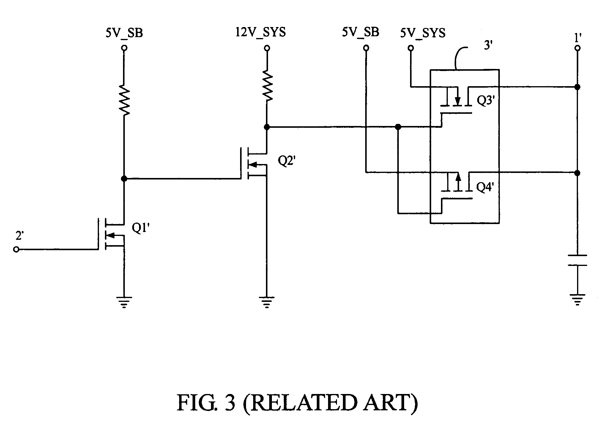
a supply voltage switching and circuit technology, applied in logic circuit coupling/interface arrangement, pulse technique, instruments, etc., can solve the problems of typical supply voltage switching disadvantage and computer downtime, and achieve the effect of greatly reducing the voltage drop of the circui
- Summary
- Abstract
- Description
- Claims
- Application Information
AI Technical Summary
Benefits of technology
Problems solved by technology
Method used
Image
Examples
Embodiment Construction
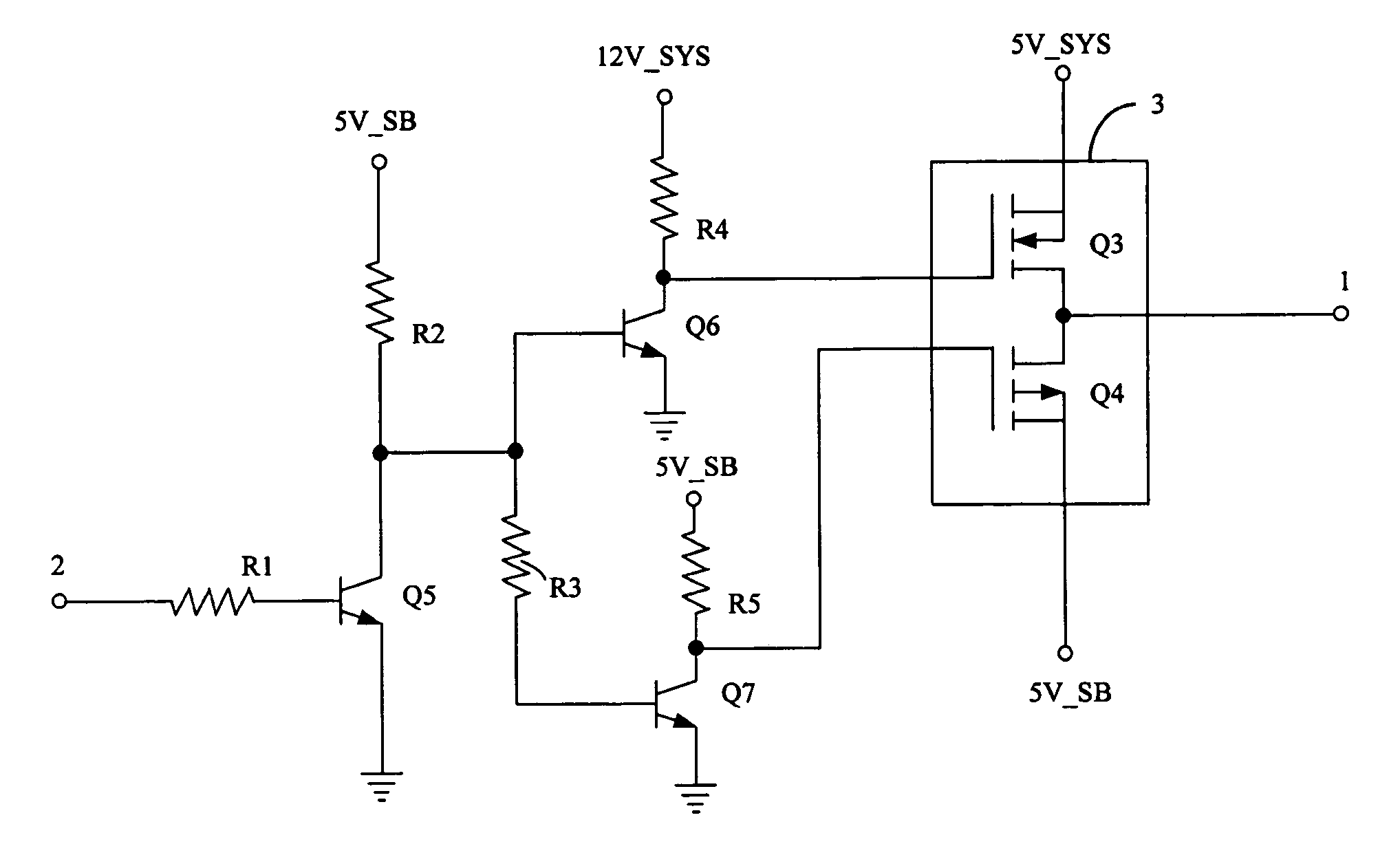
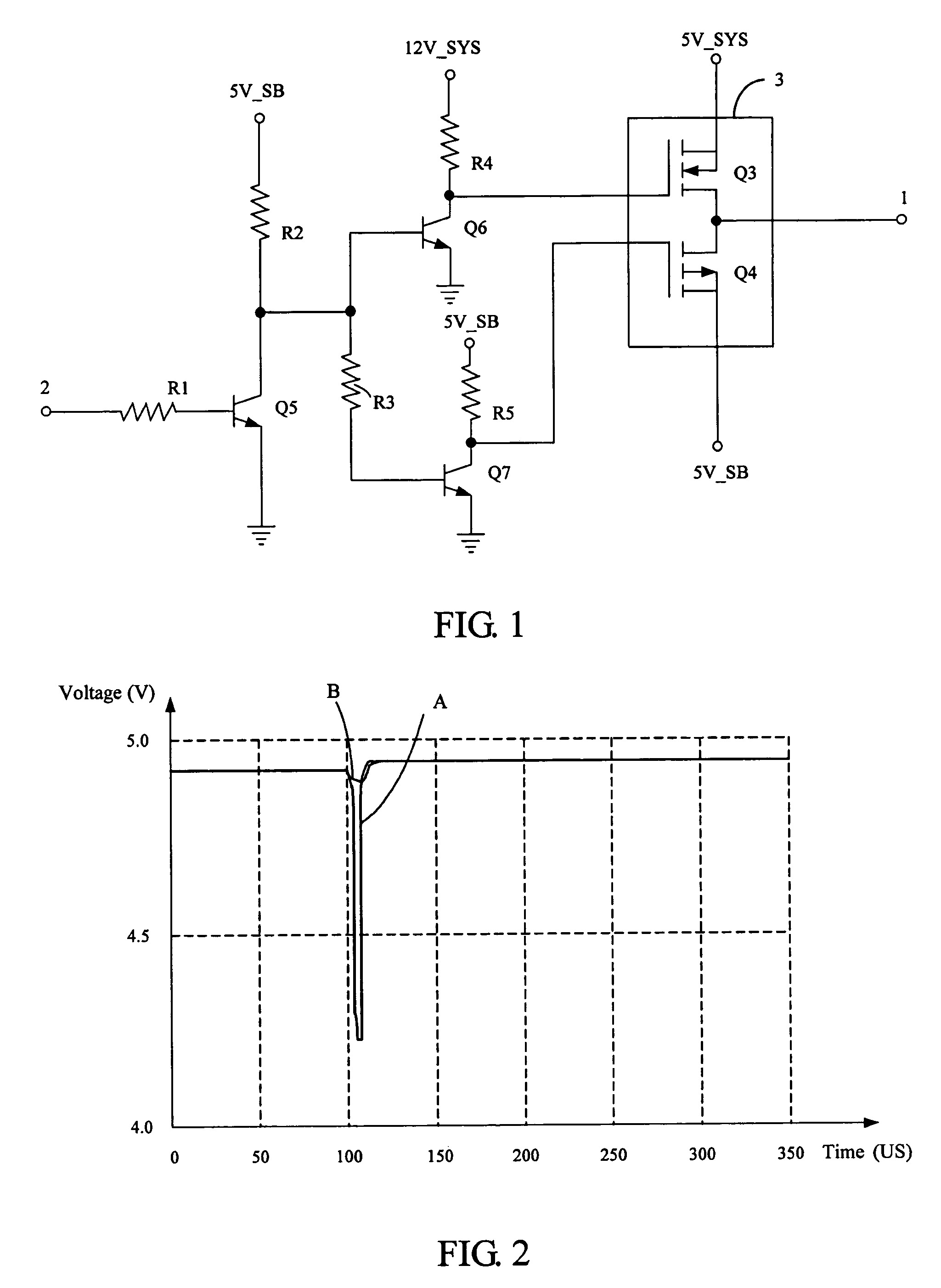
[0017]Referring to FIG. 1, a supply voltage switching circuit of a preferred embodiment of the present invention for an electronic device like a computer is shown. The supply voltage switching circuit comprises a chipset 3, a bipolar junction transistor (BJT) Q5, a BJT Q6, and a BJT Q7. The chipset 3 comprises a MOSFET Q3 and a MOSFET Q4. The MOSFET Q3 is an N-channel-strengthen MOSFET and the MOSFET Q4 is a P-channel-strengthen MOSFET. Abase of the BJT Q5 is coupled to a terminal 2 via a resistor R1 for receiving a control signal form a computer. An emitter of the BJT Q5 is grounded. A collector of the BJT Q5 is coupled to a 5V_SB via a resistor R2. Abase of the BJT Q6 is connected to the collector of the BJT Q5. An emitter of the BJT Q6 is grounded. A 12V_SYS used as one of control powers is inputted to a collector of the BJT Q6 via a resistor R4. Abase of the BJT Q7 is coupled to the base of the BJT Q6 via a resistor R3. An emitter of the BJT Q7 is grounded. A 5V_SB used as anoth...
PUM
 Abstract
Description
Claims
Application Information
 - R&D
- Intellectual Property
- Life Sciences
- Materials
- Tech Scout
- Unparalleled Data Quality
- Higher Quality Content
- 60% Fewer Hallucinations
Browse by: Latest US Patents, China's latest patents, Technical Efficacy Thesaurus, Application Domain, Technology Topic, Popular Technical Reports.
© 2025 PatSnap. All rights reserved.Legal|Privacy policy|Modern Slavery Act Transparency Statement|Sitemap|About US| Contact US: help@patsnap.com


