System and method for an IEEE 802.11 access point to prevent traffic suffering bad link quality from affecting other traffic

Inactive Publication Date: 2007-10-23
KONINKLIJKE PHILIPS ELECTRONICS NV
4 Cites 24 Cited by

AI-Extracted Technical Summary

Problems solved by technology

However, this requires dynamically setting the retransmission limit for each des...

Benefits of technology

[0011]Thus, there is a need for a way to reduce the consumption of wireless medium bandwidth by an AP's retransmission of packets over bad links. One possible approach is to dynamically lower the retransmission limit as the link quality degrades, thereby reducing the bandwidth wasted on retries. However, this requires dynamically setting the retransmission limit for each destination station and is not currently supported by the IEEE 802.11 MAC standard. The present invention provides an apparatus and method that restricts traffic on a bad link at the driver level 301 of the wireless interface 300, illustrated in FIG. 3, without requiring any change to the underlying IEEE 802.11 LAN transmission protocol. The system and method of the present invention sets an upper limit per destination station on the maximum number of packets that can be buffered by the network interface driver transmit queue, e.g., 304 and thereby achieves an upper limit on the number of packets that can exi...

Abstract

In a wireless local area network (WLAN), the present invention provides a system and method for identifying traffic suffering from bad link quality and dynamically adjusting channel access to restrict the effect of this bad link quality. The dynamic adjustment to channel access is accomplished by lowering or raising the limit on the number of packets that can be transmitted between an AP and the wireless station over the a link as determined by the link quality. The link quality is determined by tracking the number of successive packet transmission successes and errors.

Application Domain

Technology Topic

Image

  • System and method for an IEEE 802.11 access point to prevent traffic suffering bad link quality from affecting other traffic
  • System and method for an IEEE 802.11 access point to prevent traffic suffering bad link quality from affecting other traffic
  • System and method for an IEEE 802.11 access point to prevent traffic suffering bad link quality from affecting other traffic

Examples

  • Experimental program(1)

Example

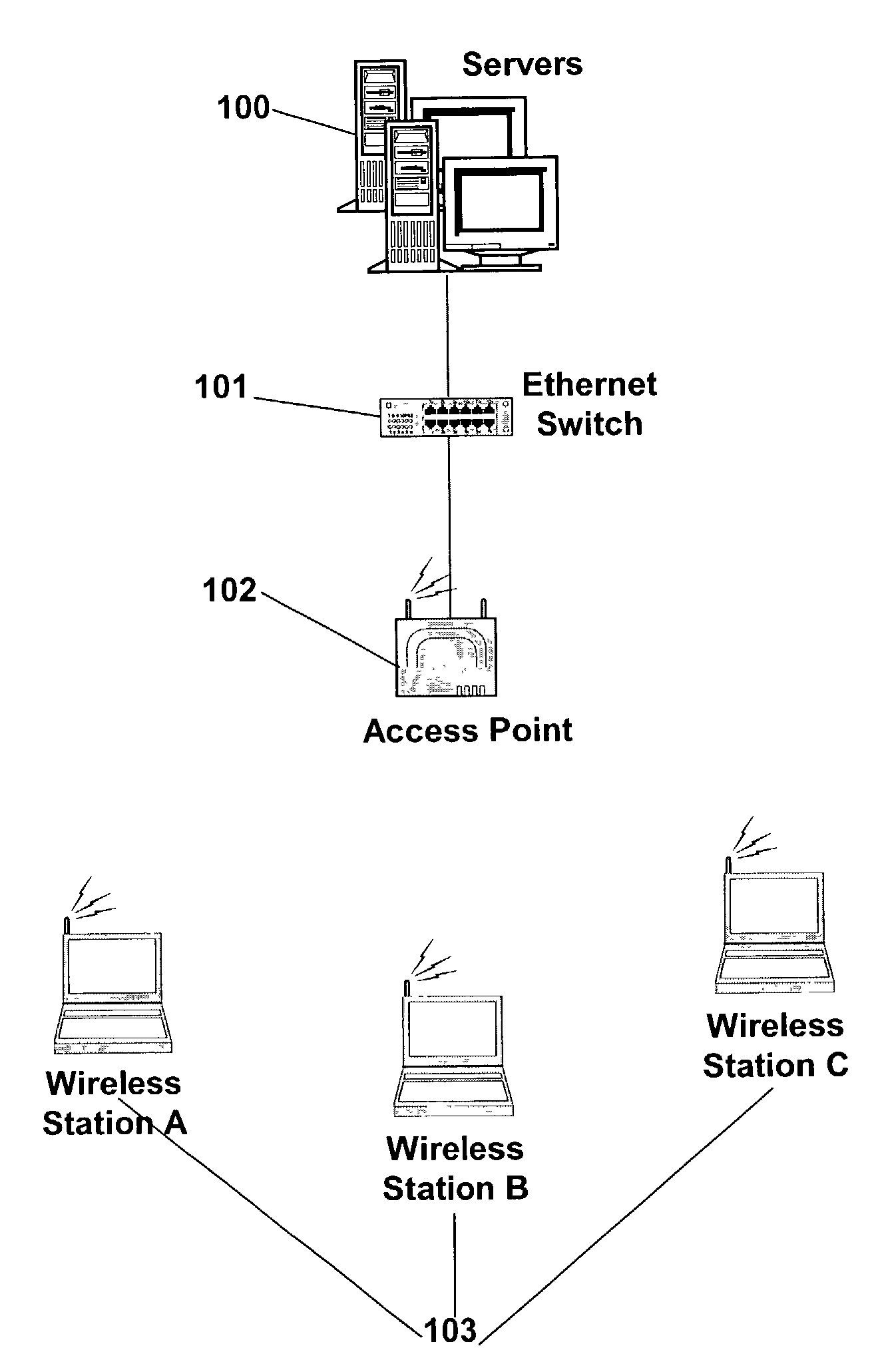
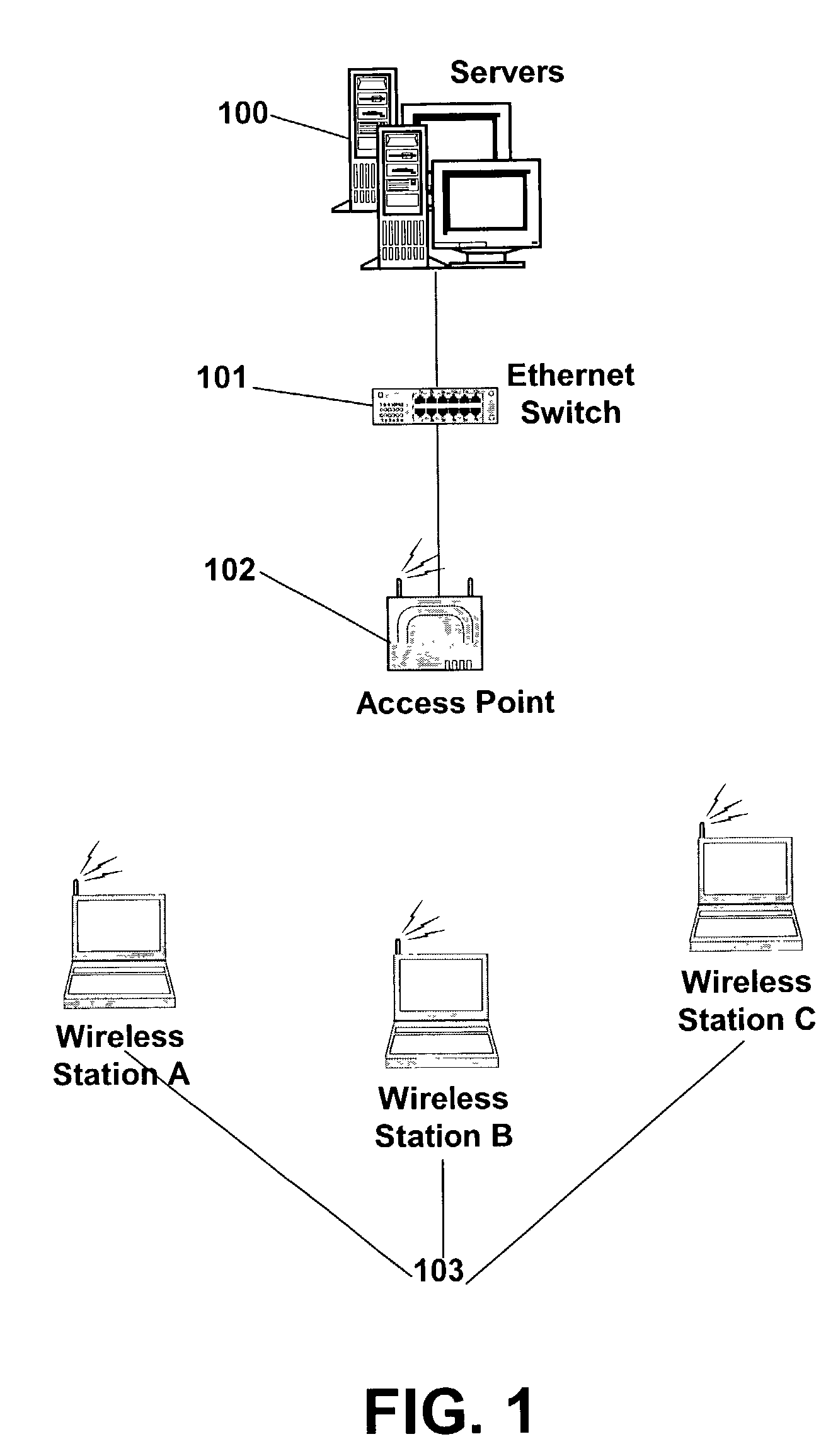
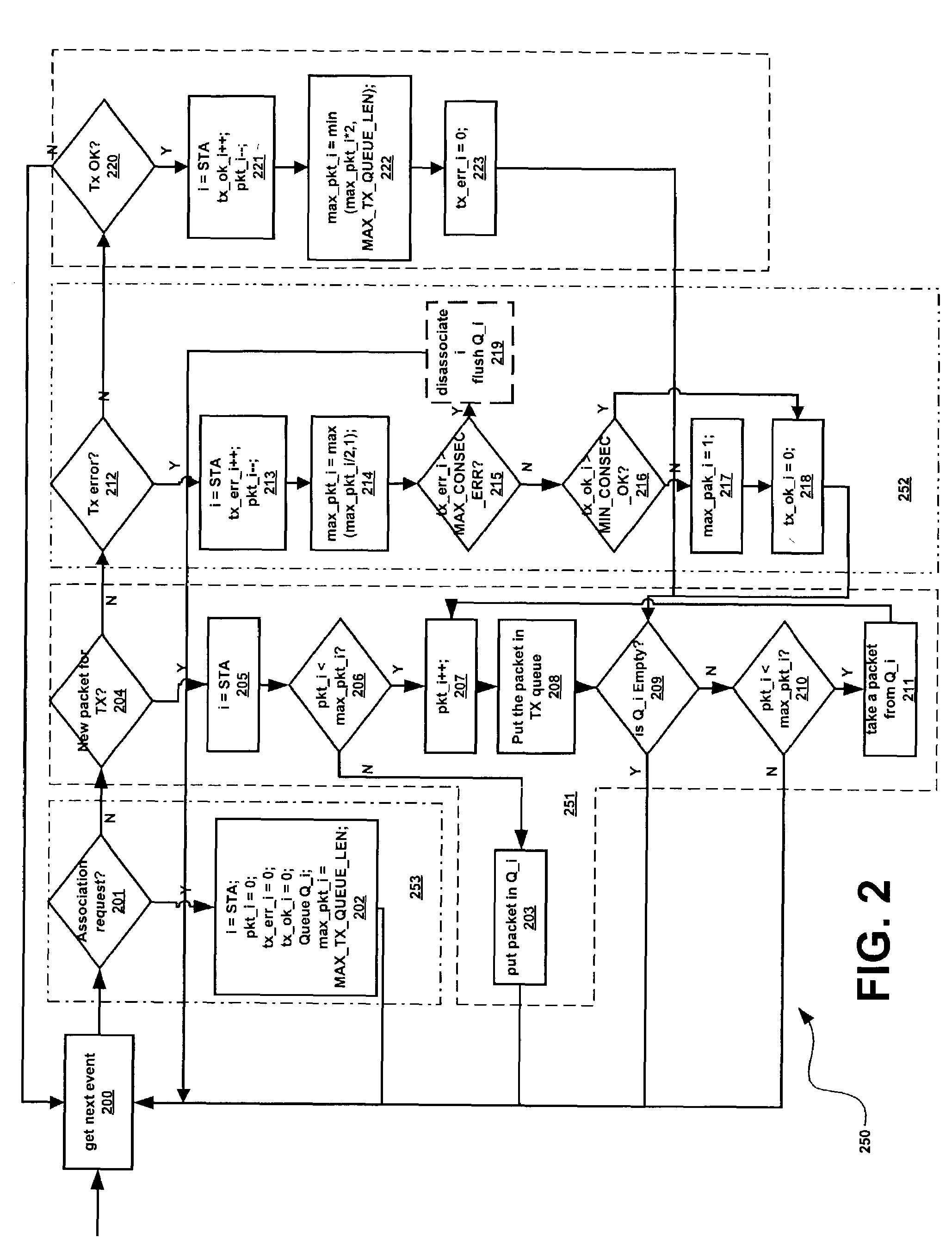
[0016]The present invention is a system and method for reducing the impact of bad links between an AP and wireless stations on other traffic competing for bandwidth over the wireless medium by dynamically manipulating the limit on the number of packets that can be queued in the AP for transmission to a given wireless station. If the link between the AP and a station is good, the limit is set to a pre-determined maximum. If the link degrades and a transmission error, this maximum is reduced in a pre-determined way to limit the impact of retransmissions on other traffic being handled by the AP.
[0017]Other refinements are provided by the preferred embodiment of the present invention. The preferred embodiment places a limit on the number of consecutive errors that can occur on a link and dissociates a station once that limit is exceeded. Further, if the link keeps going bad during a series of packet transmissions to a wireless station, the system and method of the present invention only allows one packet to be queued for transmission until the link is consistently good.
[0018]FIG. 2 is a flow of the logic of a preferred embodiment of the system and method of the present invention and FIG. 3 shows a preferred system for implementing this logic in the wireless driver of a wireless interface 300 of an AP 103. The wireless interface 300 comprises a wireless interface driver 301 interfaced to a wireless interface card 302. In the preferred embodiment, the wireless interface driver has an active queue for each active station i, j, . . . (Q_i 305 for station i, Q_j for station j, . . . ) and a shared TX queue 304 for holding a number of packets pkt_i+pkt_j+ . . . for all stations i, j, . . . that are waiting to be passed to the wireless interface card for transmission to station i. In this preferred embodiment, the system and method of the present invention begins at any point in time by obtaining the next event to process at step 200, determining the type of event and taking an appropriate action as follows:
[0019]1. If the event is a request for association with a wireless station STA at step 201, the parameters of wireless station i=STA are initialized at step 202, in particular setting the maximum number of packets max_pkt_i (that can be entered in TX queue 304 for station i to be passed to the wireless device 302 for transmission to the wireless station STA) to a predetermined value of MAX_TX_QUEUE_LEN and initializing an empty queue Q_i 304 for holding station i's packets when the maximum number that can be entered into the TX queue 304 for station i has been reached, i.e., a queue Q_i 304 for holding packets waiting to be placed into the TX queue 304 to await being passed to the device 302 for transmission to the station i. The next event is then obtained at step 200 and the process repeats.
[0020]2. If the event is a request for transmission of a new packet at step 204, the active station index i is set to wireless station STA at step 205 and if the number of station i's packets already placed into the TX queue 304 waiting to be passed to the device 302 is greater than or equal to max_pkt_i at step 206, the packet is queued in Q_i 304 at step 203. The next event is then obtained at step 200 and the process repeats. If the number of station i's packets already placed into the TX queue 304 waiting to be passed to the device 302 is less than max_pkt_i at step 206, [0021] 2a. the number of packets placed by station i into the TX queue 304 and waiting to be passed to the device 302 for transmission to station i is incremented by one at step 207, the packet is entered into the transmission queue TX 304 at step 208 and [0022] 2b. the number of packets waiting in Q_i to be placed into the TX queue 304 is checked at step 209. If there are no packets waiting to be placed into the TX queue 304, the next event is then obtained at step 200 and the process repeats. However, if there are packets for station i waiting to be placed in the TX queue 304, the number of station i's packets waiting in the TX queue 304 for passing to the device 302 for transmission to a station is checked against the dynamically set max_pkt_i at step 210 and if the maximum has not been reached a packet is dequeued at step 211 from Q_i and stage 2a above is performed with the dequeued packet. If the number of station i's packets waiting in the TX queue 304 for passing to the device 302 for transmission is at the maximum (i.e., equal to max_pkt_i) as checked at step 210, the next event is then obtained at step 200 and the process repeats. In this way the system and method of the present invention queues packets in individual Q_i queues for each station i in the driver 301 before passing them to the TX queue 304 to await transmission once the station i has queued a dynamically set maximum number of packets max_pkt_i to await being passed to the device 302 for transmission. Packets are removed at step 211 from the queue Q_i 305 and passed to the TX queue 304 to await transmission once there is room in the TX queue 304 for station i's packets, as determined at step 210. Each station has a dynamically set maximum number of packets max_pkt_i that can be in the TX queue 304 at any given time. Once this maximum number has been exceeded, packets for station i are queued in Q_i 305 of which there is one such queue for each station.
[0023]3. If the event is a transmission error at step 212, the number of consecutive transmission errors tx_err_i for this station i=STA is incremented by one, the number of packets pkt_i 303 already in the TX queue 304, is decremented by one at step 213 because the packet has been transmitted and the maximum number of packets that can be placed into TX queue 304, max_pkt_i, is dynamically reset to half the size of the previous maximum number for this station or to one (in case the maximum value was already one) at step 214. The number of consecutive transmission errors tx_err_i is checked to see if a pre-determined maximum for this parameter MAX_CONSEC_ERR has been exceeded at step 215 and, if so, the station i=STA is dissociated and the queue Q_i 304 is flushed at step 219 and the next event is then obtained at step 200 and the process repeats. If the maximum number of consecutive transmission errors tx_err_i does not exceed a predetermined maximum MAX_CONSEC_ERR at step 215, then the number of successful transmissions tx_ok_i is checked to see if a pre-determined minimum number of consecutive successful transmissions MIN_CONSEC_OK has been exceeded at step 216 and, if not, the maximum number of packets that can be place into the TX queue for station i, max_pkt_i, is set to one at step 217 and in either case the number of consecutive successfully transmitted packets tx_ok_i is set to zero at step 218 and stage 2b above is performed.
[0024]4. If the event is a successful transmission at step 220, the number of consecutive successful transmissions tx_ok_i is incremented for station i=STA and the number pkt_i of stations i's packets in the TX queue 304, is decremented by one at step 221 to reflect that a packet has been successfully transmitted and one more position has been opened up in the TX queue for packet for station i. Then the maximum number of packets max_pkt_i that can placed in TX queue 305 for station i, is dynamically set to the minimum of twice the previous value for this maximum number of packets and the predetermined value MAX_TX_QUEUE_LEN at step 222 (so that this value never exceeds MAX_TX_QUEUE_LEN). Finally the number of consecutive packet transmission errors tx_err_i is set to zero at step 223 and stage 2b above is performed. Otherwise the event is not recognized and the next event is obtained at step 200 and the process repeats.
[0025]Although a preferred embodiment has been presented, discussed above and illustrated in FIG. 2, this is by way of illustration of a best mode only. Those skilled in the art will realize that the dynamic setting of the maximum number of packets transmitted to a station based on the condition of the link can be accomplished in other ways to control the bandwidth used by a bad link between an AP and a wireless station so as to minimize the impact of retransmission on other traffic competing for this bandwidth. The illustrative example is not set forth in any limiting sense but only as the best mode known then currently known to the inventors. Obviously, many modifications and variation of the present invention are possible in light of the above teachings. It is therefore to be understood that, within the scope of the appended claims, the invention may be practiced otherwise than specifically described.

PUM

no PUM

Description & Claims & Application Information

We can also present the details of the Description, Claims and Application information to help users get a comprehensive understanding of the technical details of the patent, such as background art, summary of invention, brief description of drawings, description of embodiments, and other original content. On the other hand, users can also determine the specific scope of protection of the technology through the list of claims; as well as understand the changes in the life cycle of the technology with the presentation of the patent timeline. Login to view more.

Similar technology patents

Mobile terminal having electronic paper and method for controlling the same

InactiveUS20100184485A1Reduce consumptionDevices with multiple display unitsDevices with sensorEmbedded systemProgram control
Owner:LG ELECTRONICS INC

Classification and recommendation of technical efficacy words

  • Reduce bandwidth waste
  • Reduce consumption

Client terminal active load balancing method facing to network multimedia transmission service

ActiveCN101184031AReduce transmission nodesReduce bandwidth wasteData switching networksClient-sideProxy service
Owner:金程科技有限公司

CDMA (code division multiple access) communication method

InactiveCN102833209AIncrease the number of usersReduce Bandwidth WasteMulti-frequency code systemsTransmission path multiple useCdma systemsCarrier modulation
Owner:HARBIN INST OF TECH
Why Eureka
Try Eureka