Titanium aluminide wheel and steel shaft connection thereto

a technology of titanium aluminide and steel shaft, which is applied in the direction of blade accessories, machines/engines, waterborne vessels, etc., can solve the problems of difficult balancing between the thermal expansion of the ceramic rotor and the metal casing to maintain the clearance required, and achieve the effect of transmitting a relatively high shaft torqu

Active Publication Date: 2007-10-30
BORGWARNER INC
View PDF7 Cites 30 Cited by
  • Summary
  • Abstract
  • Description
  • Claims
  • Application Information

AI Technical Summary

Benefits of technology

[0021]Another object of the invention is to provide a rotor shaft assembly that avoids the strength limitations of a merely brazed joint, and also avoid the thermal ratcheting and imbalance found with only an interference joint. This object is achieved by a synergistic combination of brazing to support an interference fit. By this synergistic combination, an interference mounting of a TiAl wheel to a metal shaft supported by a braze mounting of the same, produces an unexpectedly strong joint that resists thermal ratcheting and imbalance.
[0022]Another object is to increase the effective surface area of a brazed joint between a TiAl rotor and a metal shaft by providing braze channels upon the jointed surface of the rotor, shaft, or both, in order to permit flow of molten braze across the surface of an interference fit, whereby an unexpectedly strong synergistic joint is formed. It is believed that the reduced contact area increases load intensity at contact points and enhances diffusion bonding.
[0023]Another object of the invention is to provide a method for the production of a rotor shaft assembly having a strong and stable joint between a TiAl turbine rotor and a metal shaft that is inexpensive, comprises few steps, and which is capable reproducibly producing rotor shaft assemblies requiring a minimum of post-production machining to balance the rotor shaft assembly.
[0024]In another object of the invention, the shaft is adapted to receive an axial protruded portion of a rotor within an axial recess disposed within one end of a shaft, and one or more substantially enclosed axial air pockets are provided between the shaft and the rotor in the jointed position. The one or more axial pockets advantageously minimize heat transfer from the rotor to the shaft during operation of the turbocharger.

Problems solved by technology

However, ceramic turbine rotors have the drawback that the rotors must be thicker than those of conventional metal rotors because of the lower toughness of ceramics.
Also, balancing the thermal expansion of the ceramic rotor and its metal casing to maintain required clearances is difficult because of the much lower thermal expansivity of ceramics.
Achieving a suitably strong joint between a TiAl rotor or wheel and a steel shaft has proved difficult, which has limited the use of TiAl rotors in production because of the additional expense and steps required to achieve a strong joint and to balance the final rotor assembly.
Direct friction welding is ineffective for mounting a TiAl rotor or wheel to a steel shaft because the structural steel is transformed from austenite to martensite upon cooling, which causes a volume expansion of the steel producing high residual stresses at the joint.
Despite the high rigidity of TiAl, its ductility at room temperature is low (about 1%), and TiAl rotors readily crack due to residual stresses.
This difficulty is compounded by the large difference between the melting points of most steels and TiAl, and the markedly different metallurgy of the two alloys.
A further problem is that during heating and cooling titanium may react with carbon in the steel to form titanium carbide at the jointing surface thereby weakening the joint.
Securely joining a TiAl rotor to a steel shaft, or to any metallic shaft is also difficult because the joint must be able to withstand the severe elevated and fluctuating temperatures that occur within an operating turbocharger.
It has therefore proved difficult to provide a particularly positive, intimate joint to connect a TiAl rotor to a steel shaft without an intermediate material of different composition.
These extra steps add time and expense to the manufacture of a turbine rotor assembly.
Furthermore, controlling the final thickness of the interposed material is difficult, and the final rotor shaft assembly must often be extensively machined to achieve balance.
All four of the above examples suffer from the drawbacks of additional steps, additional expense, and reduced dimensional accuracy.
In addition, the use of friction welding imposes geometric constraints upon the usually planar jointing surfaces, which precludes the use of certain synergistic additional jointing methods.
However, the direct vacuum brazing method suffers from the drawback that brazing must be performed under a high vacuum, which is time consuming and expensive.
In addition, achieving a reliable joint by this method may be problematic.
A further disadvantage, disclosed in U.S. Pat. No. 6,007,301 to Noda et al., of the above vacuum brazing method disclosed in Japanese Patent Disclosure No. 02-133183 is that with a planar jointing surface accurate alignment of the rotational axes of the shaft and rotor or wheel is difficult, requiring additional machining to restore balance.
Further, the alloy is brittle and prone to fracture from minor shock loads during manufacture.
However, this method suffers from the drawback that a change in rotational balance of the rotor shaft assembly commonly occurs due to microscopic relative motion of the rotor and shaft upon repeated cycles of heating and cooling, which produces thermal gradients, in a process known in the art as thermal ratcheting.
In addition, as disclosed in U.S. Pat. No. 5,174,733, forces operating at the shaft bearing assembly may weaken the heat shrink joint, requiring elaborate constraints in the bearing assembly design.

Method used


Image

  • Titanium aluminide wheel and steel shaft connection thereto
  • Titanium aluminide wheel and steel shaft connection thereto

Examples


examples

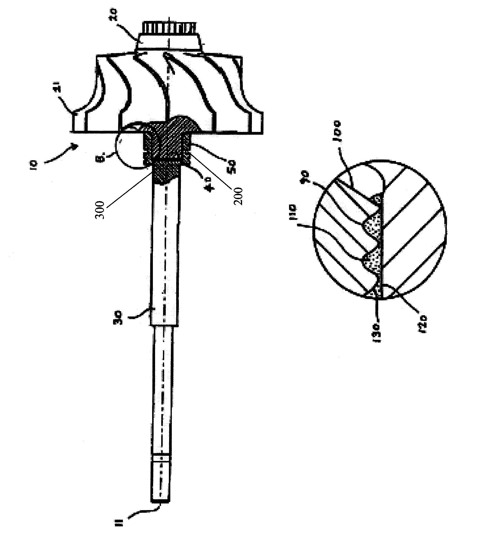
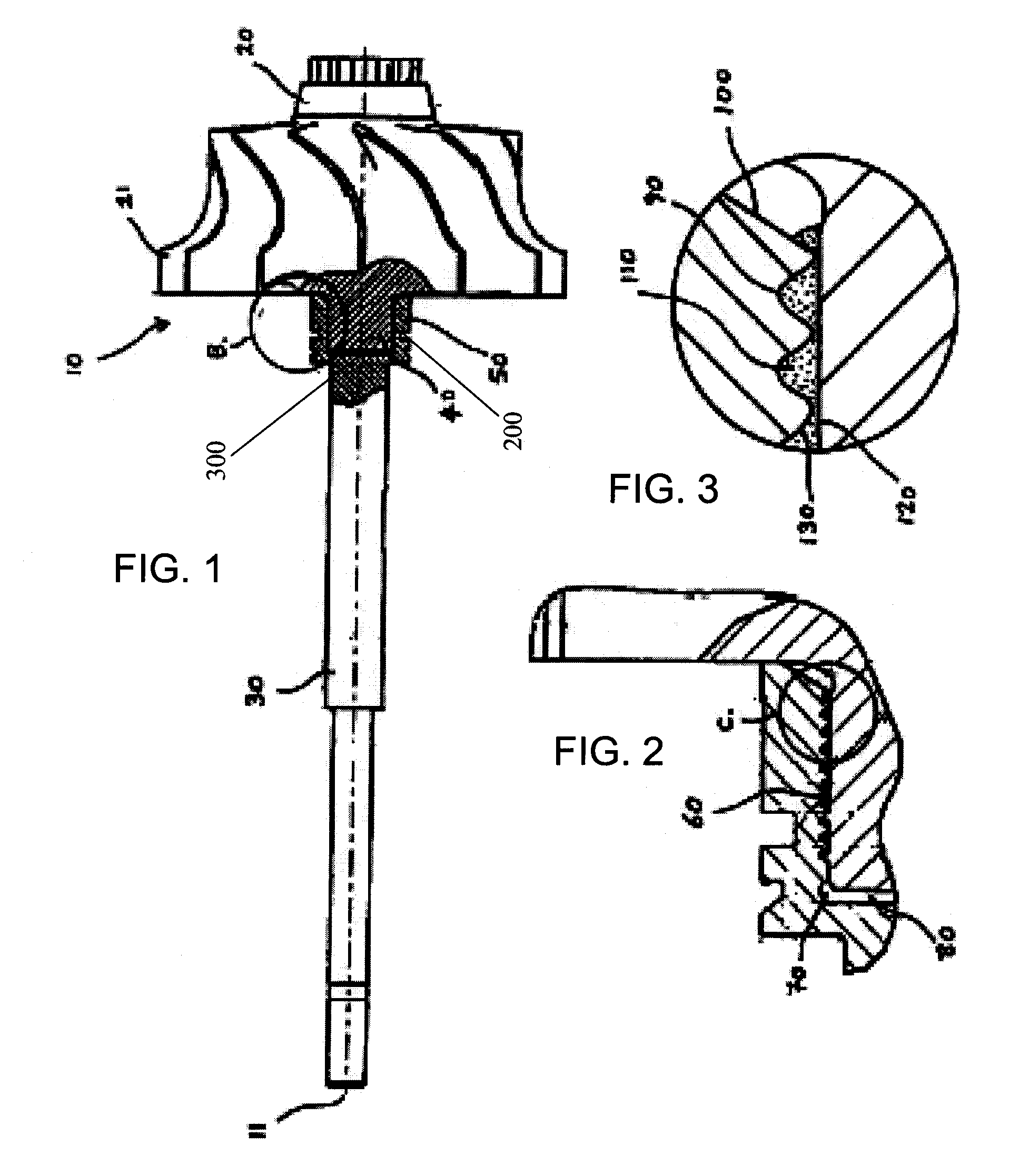
[0046]In these examples, rotor shaft assemblies are produced from a 4140 steel shaft and a TiAl rotor using a Cusil ABA braze and a moderate pressing force. The inner diameter of the shaft at the joint (D) and the length of the protruded portion of the rotor (X) were chosen as follows:

[0047]

D (inches)X (inches)Example 10.4550.435Example 20.5250.435Example 30.6540.571

[0048]At a testing temperature of 1100 F. (75% of the brazing temperature), the strength of the joint is more than three times higher than the strength obtained with heat-shrink alone in the absence of braze.

[0049]Various modifications and changes may be made by those having ordinary skill in the art without departing from the spirit and scope of this invention. Therefore, it is to be understood that the illustrated embodiments of the present invention have been set forth only for the purposes of example, and that they should not be taken as limiting the invention as defined in the following claims.

[0050]The words used i...


PUM

PropertyMeasurementUnit
temperatureaaaaaaaaaa
massaaaaaaaaaa

Abstract

Titanium aluminide (TiAl) rotor shaft assembly (10) of a type used in a turbocharger has a TiAl rotor (20) with an axially protruded portion (40) that is fixedly joined to a recessed portion (50) of a metal shaft (30) by the synergistic combination of an interference fit, such as a heat shrinkage fit, further supported by a brazed joint (60) in which a thin layer of a brazing material (110) is interposed between the surface of the protruded portion (120) and the recessed surface (130). Optionally, one or both of the jointed surfaces have braze channels (90) to facilitate braze flow within the joint. Methods for producing the rotor shaft assembly (10) and a turbocharger having the rotor shaft assembly (10) are provided.

Description

FIELD OF THE INVENTION[0001]The invention relates to a rotor shaft assembly of a type used in an exhaust driven turbocharger to drive a compressor and provide compressed air to an internal combustion engine, and to a method for the manufacture of the rotor shaft assembly. In further detail, the invention relates to a rotor shaft assembly wherein a titanium aluminide wheel has an axial projection and is joined with a rotatable steel shaft having an axial recess engaging the projection.DESCRIPTION OF THE RELATED ART[0002]Turbochargers are widely used in internal combustion engines to increase engine power and efficiency, particularly in the large diesel engines of highway trucks and marine engines. Recently, turbochargers have become increasingly popular for use in smaller, passenger car engines. The use of a turbocharger permits selection of a power plant that develops a required number of horsepower from a lighter engine. The use of a lighter engine has the desirable effect of decre...

Claims


Application Information

Patent Timeline
Patent Type & Authority Patents(United States)
IPC IPC(8): F01D5/04
CPCF01D5/025F04D29/266F05D2220/40F05D2230/237Y10T29/4932F05D2300/174Y10T29/49334Y10T29/49332F05D2260/37F16D1/027
Inventor DECKER, DAVID M.
Owner BORGWARNER INC
Why Eureka
Try Eureka