Selective shield/material flow mechanism

a flow mechanism and shield technology, applied in the direction of electrolysis components, coatings, cell components, etc., can solve the problems of difficult to achieve uniform electrodeposition, adversely affect the electroplating process, and relatively complex electroplating process, etc., to slow slow down or increase the solution flow, the effect of increasing the thickness and rate of the plating

Inactive Publication Date: 2007-10-30
GLOBALFOUNDRIES INC
View PDF6 Cites 13 Cited by
  • Summary
  • Abstract
  • Description
  • Claims
  • Application Information

AI Technical Summary

Benefits of technology

[0006]Another object of the present invention is to selectively and controllably adjust the amount of electric flux passing towards selected areas of a workpiece, during an electroplating process, in order to deposit a metal film or alloy with a uniform thickness across the workpiece. This apparatus could also be used to regulate solution flow in an electroless plating deposition bath which would in turn make the bath more capable of depositing in small through holes.
[0008]Another object of this invention is provide an infinitely adjustable mechanism that can selectively isolate areas to be electroplated.
[0011]With a preferred embodiment of the invention, described in detail below, the selective shield / material flow assembly is used to selectively isolate an area of the workpiece from plating by use of an individual adjustable selective shield / material flow mechanism. The selective flow material flow assembly can comprise one or more selective shield material flow mechanisms. The selective shield material flow assembly can be adjusted selectively on one, two, or multi axes. In another embodiment, the shielding, in the case of electroless plating, also slows or increases solution flow to areas of the plating surface and thus lowers or increases plating thickness and rates. The shielding or baffling also slows / isolates solution flow to the plating surface and thus lowers or raises plating thickness / rates. This causes more plating uniformity in panel or pattern plating equipment.

Problems solved by technology

However, the electroplating process is relatively complex, and various naturally occurring forces may adversely affect the electroplating process.
Most significantly, the electrical current or flux path between the anode and the cathode may spread or curve, making it difficult to achieve uniform electrodeposition.

Method used


Image

  • Selective shield/material flow mechanism
  • Selective shield/material flow mechanism
  • Selective shield/material flow mechanism

Examples


Embodiment Construction

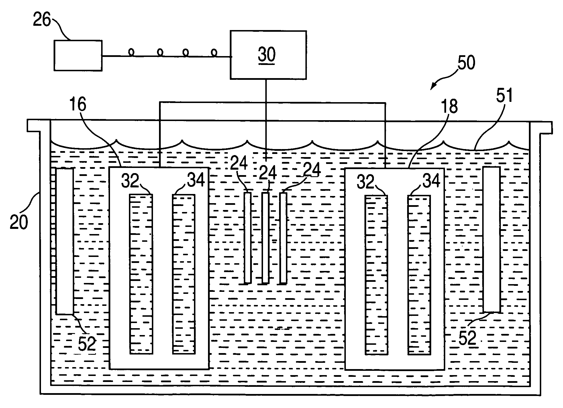
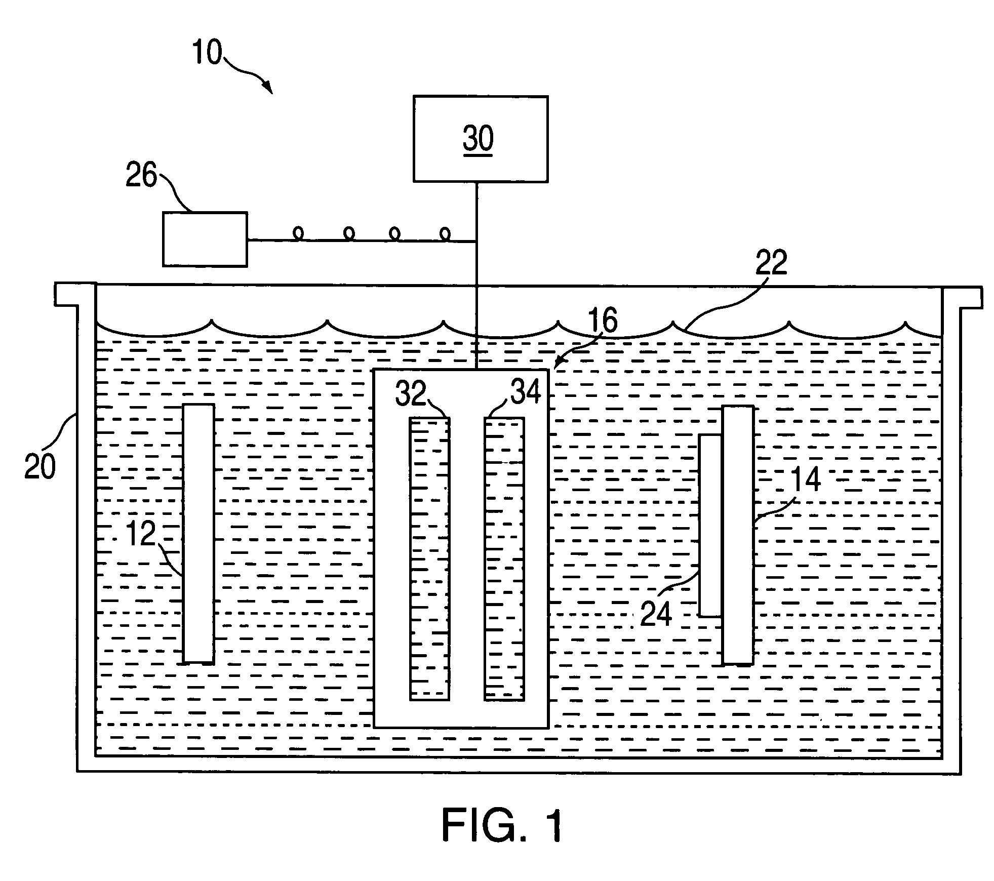
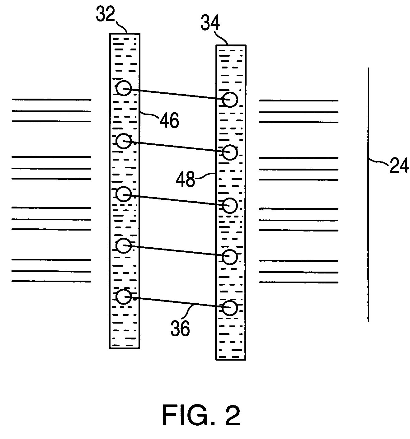
[0019]FIG. 1 illustrates electroplating apparatus 10 generally comprising anode 12, cathode 14, and selective shield / material flow assembly 16. FIG. 1 also shows receptacle 20, electroplating solution 22, workpiece 24, selective shield / material flow assembly control 26, and selective shield / material flow assembly support 30. With reference to FIGS. 1-4, selective shield / material flow assembly 16 preferably comprises first and second individual selective shield / material flow mechanism 32 and 34, and connecting means 36 such as a series of connecting links. Each selective shield / material flow mechanism 32, 34, in turn, includes a support member or frame 40 and a series of slats 42 as shown in FIG. 4.

[0020]Returning to FIG. 1, receptacle 20 holds the electroplating solution 22, which contains the ions of the metal or alloy to be deposited on the workpiece 24. Any suitable receptacle and electroplating solution may be used in the practice of this invention. Preferably, the receptacle is...


PUM

PropertyMeasurementUnit
sizesaaaaaaaaaa
electric fieldaaaaaaaaaa
sizeaaaaaaaaaa

Abstract

An apparatus and method for plating a workpiece. The apparatus comprises, generally, an anode, a cathode, and a selective anode shield / material flow assembly. In use, both the anode and the cathode are immersed in a solution, and the cathode is used to support the workpiece. During an electroplating process, the anode and the cathode generate an electric field emanating from the anode towards the cathode, to generate a corresponding current to deposit an electroplating material on the workpiece. The selective shield / material flow assembly is located between the anode and the cathode, and forms a multitude of adjustable openings. These opening have sizes that are adjustable during the electroplating process for selectively and controllably adjusting the amount of electric flux passing through the selective shield / material flow assembly and the distribution of the electroplating material on the workpiece. The selective shield / material flow assembly can also be used with an electroless plating system. At least one selective shield material flow mechanism is used in a selective shield material flow assembly.

Description

[0001]This application is a divisional of U.S. application Ser. No. 09 / 871,557, filed May 31, 2001, now U.S. Pat. No. 6,746,578.BACKGROUND OF THE INVENTION[0002]This invention generally relates to electroplating and electroless plating apparatus and methods.[0003]Electroplating is a common process for depositing a thin film of metal or alloy on a substrate such as, for example, a variety of electronic components and semiconductor chips. In a typical electroplating apparatus or system, the substrate is placed in a suitable electrolyte bath containing ions of a metal to be deposited. The substrate is connected to the negative terminal of a power supply to form a cathode, and a suitable anode is connected to the positive terminal of the power supply. Electrical current flows between the anode and cathode through the electrolyte and metal is deposited on the substrate by an electrochemical reaction.[0004]In many electronic components, it is desirable to deposit the metal film with a uni...

Claims


Application Information

Patent Timeline
Patent Type & Authority Patents(United States)
IPC IPC(8): C25D5/00C25D17/00C25D5/08C25D7/12C25D17/12C25D21/12
CPCC25D5/00C25D17/12C25D5/003C25D17/008C25D21/12Y10S204/07
Inventor BARRESE, RALPH A.GAJDORUS, GARYHOPKINS, ALLEN H.KONRAD, JOHN J.SCHAFFER, ROBERT C.WELLS, TIMOTHY L.
Owner GLOBALFOUNDRIES INC
Why Eureka
Try Eureka