Method and apparatus for measuring conductivity of powder materials using eddy currents

a technology of conductivity measurement and powder material, which is applied in the direction of instruments, specific gravity measurement, carbides, etc., can solve the problems of relatively small contact area and inability to accurately determine contact measurements

Inactive Publication Date: 2007-10-30
ENERIZE CORP
View PDF6 Cites 13 Cited by
  • Summary
  • Abstract
  • Description
  • Claims
  • Application Information

AI Technical Summary

Benefits of technology

[0059]The apparatus preferably includes a vibration device for compacting the powder sample, such as a flask including an electromagnet, and a system of springs whose upper base is comprised of a magnetic wafer affixed to the springs, wherein a bottom of the flask is placed on the magnetic wafer, a mechanism for fixing the flask bottom on the magnetic wafer, and a current pulse series generator that powers the electromagnet, wherein the springs attach to a bottom of the sampling container. The system of springs can provide a weight of the powder, wherein the continuous electrically conductive layer is disposed on an outside surface of a lower portion of the sampling container is galvanically linked with the system of springs.

Problems solved by technology
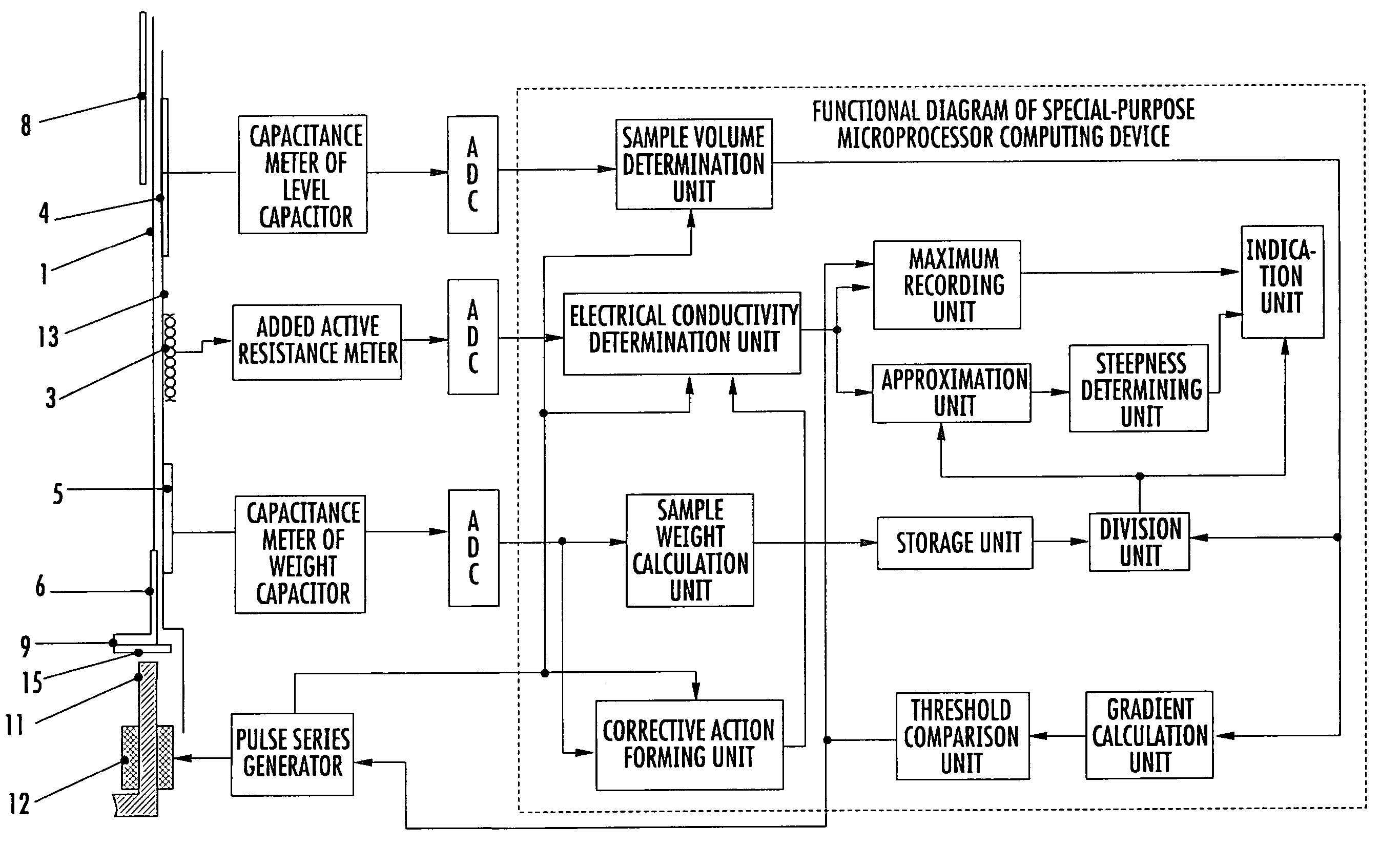
Contact measurements fail to accurately determine this parameter for powder-like materials as the electrical resistance of the grains chain to the current that flows in succession through them is mainly determined by the contact resistances in places the grains contact each other, while these resistances substantially exceed their inner resistances.
First, the contacting grains, when the powder is of minor density (within the operating range of the powder densities being used for electrode coats of the chemical power sources) obtained by vibration compacting, have relatively small areas of contact there among.

Method used


Image

  • Method and apparatus for measuring conductivity of powder materials using eddy currents
  • Method and apparatus for measuring conductivity of powder materials using eddy currents
  • Method and apparatus for measuring conductivity of powder materials using eddy currents

Examples


example 1

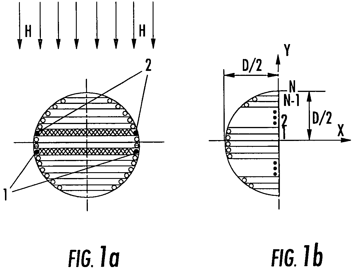
[0149]The magnetic field of a circular coil with current I of radius R is first considered. It is known that the magnetic field intensity on the coil axis, that is at ρ=0 is determined by the formula:

[0150]Hz=I2⁢R2[R2+z2]3 / 2,(11)

where ρ, z are coordinates of the cylindrical system of coordinates whose center is coincident with the center of the coil. The field intensity in the coil center.

[0151]Hz⁡(z=0)=I2⁢R.(12)

[0152]The relationships Hz / Hz(z=0) as a function of the coordinate z normal to the coil plane is now considered.

[0153]The respective values of relative intensity Hz / Hz(z=0) calculated according to formulas (11) and (12) as a function of the rated coordinate z / R are given in Table 1. According to Table 1 the magnetic field intensity at distance z along the coil axis equal to its diameter is 8.9% relative to the intensity value in the coil center.

[0154]

TABLE 1Hz / Hz(z = 0)z / R100.7150.50.3541.00.1711.50.0892.0

example 2

[0155]The formula for determining the capacitance per length unit (1 m) between infinitely long cylindrical casings of circular cross-section in case when one of the casings is arranged inside of the other (see FIG. 7) has the following form:

[0156]Cl=1⁢m=2⁢⁢π⁢⁢ɛ0⁢ɛArch⁢R12+R22-d22⁢R1⁢R2,(13)

where l is the coordinate along the cylinder generating line; ε is the dielectric permeability of the material between the cylindrical casings, R1 and R2 are the radiuses of the casings, d is the shift of the casing axes, ε=8.854*10−12 F / m is the dielectric constant of free space.

[0157]Value Arch x is Expressed as Follows:

y=Archx=ln(x−√{square root over (x2−1)}), for x≧1 and −∞

y=Archx=ln(x+√{square root over (x2−1)}), for x≧1 and 0≦y≦∞.  (15)

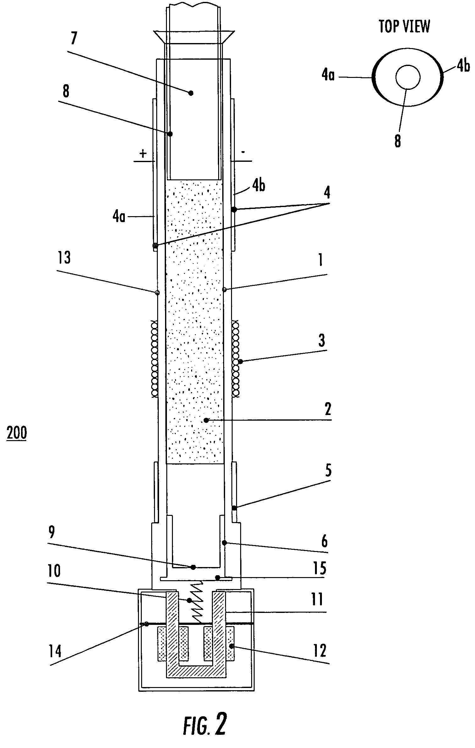
[0158]In one case R2=12 mm; R1=13.5 mm+T0=14.5 mm (T0 is the thickness of the casing wall in the area of the outer wafer of the sample weight measuring capacitor T0=1 mm). The outer wafer is arranged in the casing wall recess. The casing wall thick...

example 3

[0164]Two circular circuits with different radii and parallel axes are now considered as shown in FIG. 9. Value x we shall take equal to zero, in this case Θ=π / 2. The radius of the eddy-current circuit shall be taken equal to the inner sampler radius R2=11 mm. The coil radius of the eddy-current sensor shall be taken equal to the inner radius of casing R plus the thickness of the casing wall in the area of the winding location T0: R1=R+T0=13.5 mm+1 mm =14.5 mm. It should be noted that beyond the eddy-current sensor winding the thickness of the casing wall equals 2 mm.

[0165]In case d1−R2=3.5 mm, the mutual induction can be found by the following formula:

[0166]M=π⁢⁢μ0⁢R22R1⁢⁢∑n=0∞⁢⁢(-1)n⁢⁢(2⁢n+1)!22⁢n+1⁢(n!)2⁢⁢(dR1)2⁢n⁢⁢F(⁢n+12,⁢n+32,2,R22R12)⁢⁢P2⁢n(⁢cos⁢⁢Θ),(17)

where F is a hyper geometric series, P2n is Legandre's polynom.

[0167]The hyper geometric series of the variable x and of the parameters a, B, C is determined by the following formula:

[0168]F⁡(a,b,c,x)=1+ab1·c⁢x+a⁡(a+1)⁢b⁡(b+1)...


PUM


Abstract

A method and related apparatus for non-contact measurement of electrical conductivity of powder-like materials using eddy currents includes the steps of placing a powder to be measured in a hollow dielectric sampling container, the sampling container disposed and freely axially moving within an outer dielectric housing. An eddy-current sensor including a winding is arranged on an outside surface of the housing. Current is forced in the winding to excite the powder to generate eddy currents. The introduced active resistance is measured at the eddy-current sensor and an electrical conductivity of the powder is determined using the measured active resistance. The powder is preferably vibration compacted and the density and electrical conductivity determined at a plurality of stages during the vibration compacting step.

Description

CROSS-REFERENCE TO RELATED APPLICATIONS[0001]This application incorporates by reference in its entirety and claims priority to Provisional Application No. 60 / 616,380 filed on Oct. 6, 2004.FIELD OF THE INVENTION[0002]The invention relates to the methods and apparatus for measuring the electrical properties of non-metallic powder-like materials using eddy currents.BACKGROUND OF THE INVENTION[0003]The electrical conductance of electrode and electrolyte materials can be critical parameter for a variety of devices, including lithium-based batteries, supercapacitors and certain fuel cells. Contact measurements fail to accurately determine this parameter for powder-like materials as the electrical resistance of the grains chain to the current that flows in succession through them is mainly determined by the contact resistances in places the grains contact each other, while these resistances substantially exceed their inner resistances. This is explained by two reasons. First, the contactin...

Claims


Application Information

Patent Timeline
Patent Type & Authority Patents(United States)
IPC IPC(8): G01N27/00G01R27/00G01R33/14C01B32/949
CPCC01B31/04G01N9/36G01N27/90G01N2015/0096G01N15/0656
Inventor REDKO, VOLODYMYRKHANDETSKYY, VOLODYMYRNOVAK, PETERSHEMBEL, ELENAKOHARA, SATOSHI
Owner ENERIZE CORP
Why Eureka
Try Eureka