
Polar modulator and a method for modulation of a signal

a modulator and signal technology, applied in the field of polar modulators and signal modulation methods, can solve the problems of data errors, changes in the frequency spectrum of emitted signals, and requirements for the last mixer stage, so as to prevent spurious data transmission, reduce quantization noise, and prevent non-linearity

Inactive Publication Date: 2007-10-30
INTEL CORP
View PDF5 Cites 18 Cited by
  • Summary
  • Abstract
  • Description
  • Claims
  • Application Information

AI Technical Summary

Benefits of technology

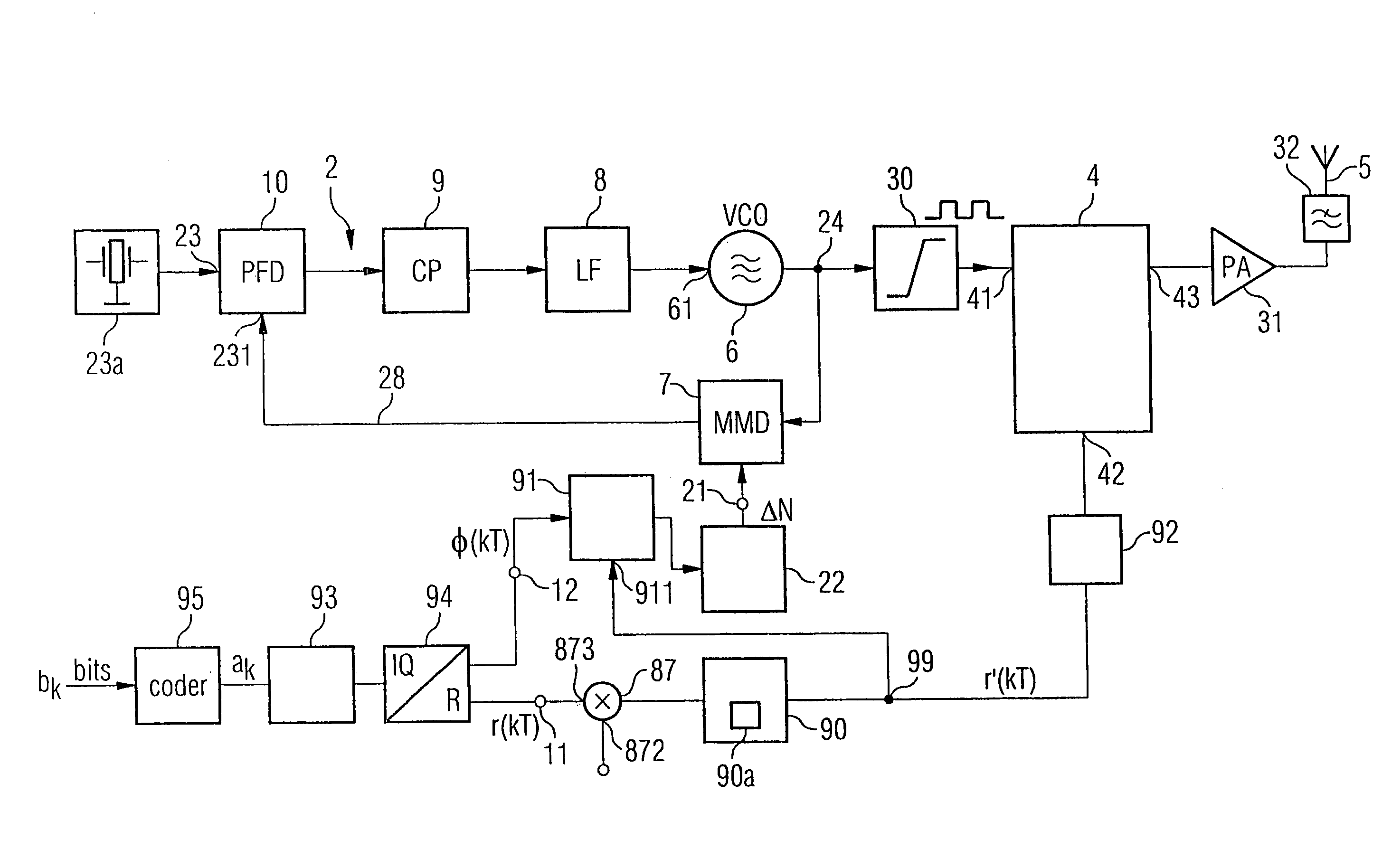
[0012]Aspects of the present invention can provide a polar modulator which is suitable for low supply voltages and can be designed in a space-saving manner, for example in the form of an integrated circuit in a semiconductor body. Additionally, aspects of the invention can specify a method for modulation of a signal, which can be carried out with a low power consumption.
[0028]The sigma-delta modulator can use the amplitude modulation signal to produce an oversampled regulation signal for adjustment of the duty ratio in the pulse width modulator. This makes it possible to reduce the quantization noise, and to prevent spurious data transmission.
[0029]In a further aspect of the invention, a predistortion unit is connected between the regulation input of the pulse width modulator and the second signal input, in order to supply an amplitude modulation signal. In one preferred embodiment, this predistortion unit has a table in which values are stored which represent a reciprocal function of a trigonometric function, such as a sine or a cosine function. The predistortion unit prevents non-linearity resulting from the signal processing in the pulse width modulator. In this context, it is likewise expedient to provide a phase compensation unit, which is arranged between the first signal input of the polar modulator and the control input of the phase locked loop and has an open-loop and closed-loop control input which is coupled to the regulation input of the pulse width modulator. This compensates for any amplitude / phase distortion resulting from the processing of the phase-modulated signal in the pulse width modulator.

Problems solved by technology

The problem with this solution is the requirements for the last mixer stage.
The distortion results in data errors, and changes the frequency spectrum of the emitted signal.
Furthermore, a polar modulator such as this cannot be designed using new types of CMOS technologies with low supply voltages in the range from 1.5 V to 2.5 V.

Method used


Image

  • Polar modulator and a method for modulation of a signal
  • Polar modulator and a method for modulation of a signal
  • Polar modulator and a method for modulation of a signal

Examples


Embodiment Construction

[0044]The present invention will now be described with reference to the attached drawings, wherein like reference numerals are used to refer to like elements throughout. It will be appreciated by those skilled in the art that the invention is not limited to the exemplary implementations and aspects illustrated and described hereinafter.

[0045]FIG. 1 shows a polar modulator according to the invention, which can be integrated in as an integrated circuit in a semiconductor body. Contact points are applied to the surface of the semiconductor body and supply signals to the integrated circuit. The technology used in this case differs, depending on the requirements. For example, the polar modulator according to the invention may be designed using CMOS technology. Silicon, gallium arsenide or silicon germanium (Si Ge) may be used as the semiconductor material, although other semiconductor materials are, of course, also feasible.

[0046]The invention proposes that the amplitude of the signal to...


PUM


Abstract

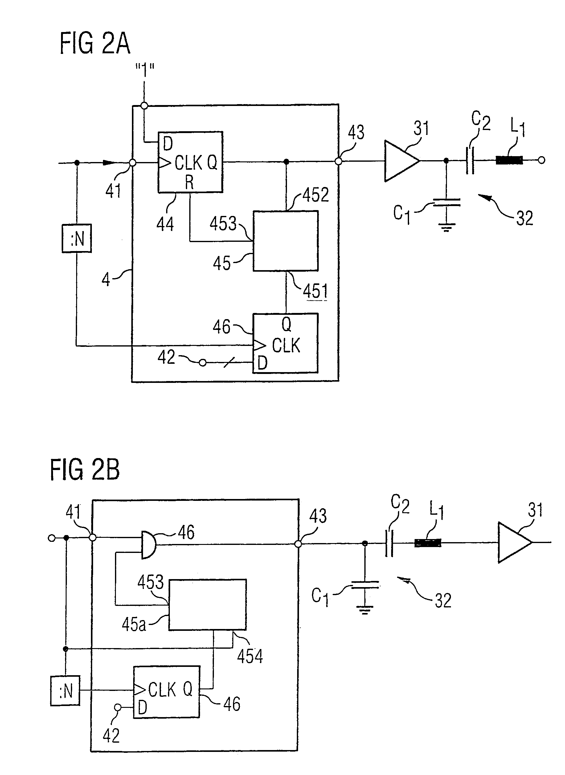
A polar modulator contains a phase locked loop which is designed to emit a radio-frequency signal at one frequency to one output, with the frequency being derived from the reference signal and from a phase modulation signal at a control input of the phase locked loop. The modulator additionally has a second signal input for supplying an amplitude modulation signal. The second signal input is connected to a control input of a pulse width modulator, one of whose signal inputs is coupled to the output of the phase locked loop. The pulse width modulator is designed to vary the duty ratio of a signal which is applied to the signal input, with this variation being adjustable via a regulation signal at the control input. A filter can be connected downstream from the output of the pulse width modulator and suppresses higher harmonic components in a signal which can be tapped off at the output of the pulse width modulator. The amplitude of an output signal is thus modulated by carrying out pulse width modulation and by subsequent suppression of higher-level frequency components.

Description

REFERENCE TO RELATED APPLICATIONS[0001]This application claims the benefit of the priority date of German application DE 10 2004 060 698.6, filed on Dec. 16, 2004, the contents of which are herein incorporated by reference in their entirety.FIELD OF THE INVENTION [0002]The invention relates to a polar modulator, and to a method for modulation of a signal.BACKGROUND OF THE INVENTION[0003]In modern communication systems, the information to be transmitted is coded both in the phase and in the amplitude of a signal. This means that it is possible to achieve considerably higher data transmission rates than those with pure amplitude and / or phase modulation. Examples of modulation types such as these are PSK modulation (Phase Shift Keying). These include, inter alia π / 4-DQPSK, 8-DPSK or 8-PSK modulation. Quadrature amplitude modulation methods (QAM) also code the information to be transmitted both in the amplitude and in the phase. In contrast to analog amplitude or frequency modulation, t...

Claims


Application Information

Patent Timeline
Patent Type & Authority Patents(United States)
IPC IPC(8): H03C3/38
CPCH03C5/00H03F3/24H04L27/361H03K7/08H03F2200/351H03F2200/331
Inventor PUMA, GIUSEPPE LI
Owner INTEL CORP
Learn More