Direct contact cooling liquid embedded package for a central processor unit

a technology of embedded packaging and cooling liquid, which is applied in the direction of cooling/ventilation/heating modification, electrical apparatus casing/cabinet/drawer, semiconductor/solid-state device details, etc., can solve the problems of inability to meet the requirements of high-power electronic components such as computer server processors, the reliability of electronic systems will suffer, and the practical application limit has reached the limit, etc., to achieve high mechanical loading, improve heat transfer, and improve the effect of heat flux

Active Publication Date: 2007-10-30
ORACLE INT CORP
View PDF28 Cites 32 Cited by
  • Summary
  • Abstract
  • Description
  • Claims
  • Application Information

AI Technical Summary

Benefits of technology

[0006]According to an embodiment of the present invention, a PGA (pin grid array) flip-chip server CPU is attached to the cooling liquid in the system through mechanical connection of a specially designed socket unit. In addition to providing substantial heat removal ability, the packaging system of the present invention eliminates the need for a fan and heat sink air cooling system. The space traditionally occupied by these cooling components is therefore beneficially reduced. A much denser design of server boards with a larger number of components per board and a higher number of server processors can be achieved beyond that which is currently available. Other packaging systems than the flip-chip system can be used with the present invention such as a PGA socket, μPGA socket, PPGA socket, LGA socket or the like.
[0008]Microchannels built into the substrate and cavity portion of the package provides the pathway for an inlet and an outlet of the cooling liquid into the silicon processor portion of the package. Flow of the cooling liquid over the silicon die takes away heat generation in the die and heated liquid is forced out of the package cavity due to the pressure gradient of the liquid cooling system. The cooling liquid can be a dielectric liquid that is thermally conductive but electrically resistive, to not cause any electrical shortage when it comes in contact with the silicon die or any other electrical portion of the package. The liquid flow rate and choice of cooling liquid is selected to prevent any massive boiling of the cooling liquid over the silicon die. Additionally, the cooling system pressure difference can be designed to make the entire cooling system orientation-independent for cooling purposes. A self-locking mechanism can be used to prevent introduction of any foreign material or particles into the package, and any spillage of the cooling liquid in case of a rework process.
[0009]According to an embodiment of the present invention, the direct contact cooling liquid embedded package for a CPU is an improved liquid-based cooling system that takes a cooling liquid to the heart of the heat generating component of the central processor unit. It can radically improve heat transfer for high heat flux processors by providing direct contact between the heat generating silicon die and the cooling liquid. The direct contact liquid cooling package system of the present invention substantially removes any issues such as hot spots, thermal mismatch, high mechanical loading, or the like that should ideally be managed for traditional air cooling or indirect liquid cooling of the processors. Additionally, the cooling system of the present invention substantially removes the need for a fan / heat sink assembly and therefore frees a great deal of space over the board and in the server. The cooling system of the present invention is either unique to the server or may be tied into the data-center central cooling system.
[0010]The cooling system of the present invention also uses the existing package-to-board practice of using sockets and therefore the entire cooling system is embedded into the processor-to-board assembly. From the end user's point of view, there is a tremendous amount of simplification of board design as the bulky fan and heat sink assemblies are removed. The replacement, according to the present invention, is a central liquid cooling system that can be made redundant to substantially prevent any reliability issues in the field.

Problems solved by technology

Removal of heat has become one of the most important and challenging issues facing computer system designers today.
As the rate of power dissipation from electronic components such as high performance server processors and other such integrated circuits continues to increase, standard conduction and forced-air convection fan air cooling techniques no longer provide adequate cooling for such sophisticated electronic components.
The reliability of the electronic system will suffer if high temperatures at hot spot locations are permitted to persist.
Conventional thermal control schemes such as air-cooling with fans, thermoelectric cooling, heat pipes, and passive vapor chambers have either reached their practical application limit or are soon to become impractical for high power electronic components such as computer server processors.
When standard cooling methods are no longer adequate, computer manufacturers are forced to reduce the speed of their processors to match the capacity of existing cooling apparatuses, accept lower component reliability due to inadequate cooling using existing cooling apparatus, or delay release of products until a reliable cooling apparatuses for removal of heat from high heat dissipating processors are made available.
Additionally, thermal management of high heat flux CPUs and other integrated circuits may require the use of bulky heat fans and heat sink assembly units, which have limited the ability of computer server manufacturers to adequately increase the capacity of their systems due to space limitations.
A number of attempts to incorporate liquid for cooling of high powered processors in the form of submerged liquid, liquid spray cooling, refrigeration cooling, and the like have been tried in the past, but none of the existing active liquid cooling solutions have been successfully utilized outside of their specific design conditions.

Method used


Image

  • Direct contact cooling liquid embedded package for a central processor unit
  • Direct contact cooling liquid embedded package for a central processor unit
  • Direct contact cooling liquid embedded package for a central processor unit

Examples


Embodiment Construction

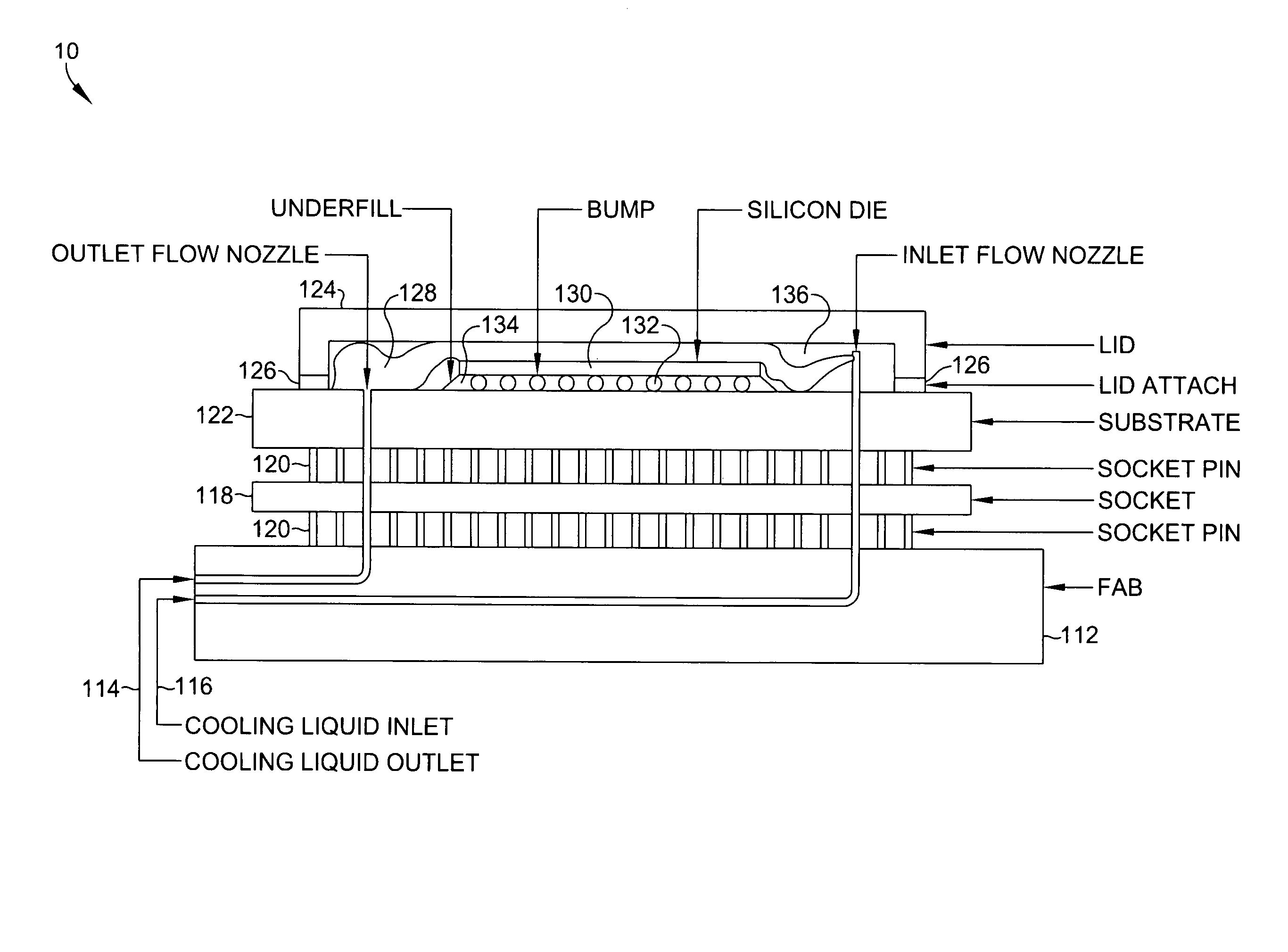
[0014]Referring now to FIG. 1, a package assembly 10 for an integrated circuit employing direct contact liquid cooling includes a board or “fab”112 having a liquid coolant inlet 116 and a liquid coolant outlet 114, a socket 118 coupled to the board 112, and a package substrate 122 coupled to the socket 118. In the expanded cross-sectional view of FIG. 1, the board 112, the socket 118, and package substrate 122 are coupled together through socket pins 120. In actual usage, the board 112, the socket 118, and the package substrate 122 are in closer physical contact than is shown in FIG. 1. The expanded cross-sectional view of FIG. 1 is provided for ease of understanding the relationship of the individual components of the present invention only. A first microchannel allows liquid coolant 128 to flow from the liquid coolant inlet 116 through the board 112, the socket 118, and the package substrate 122. A second microchannel allows liquid coolant 128 to flow through the package substrate...


PUM


Abstract

A direct contact cooling liquid embedded package design for use with a computer central processor unit is suitable for thermal management of high heat dissipation electronic components such as server processors. The direct contact cooling liquid embedded packaged CPU has mechanical coupling and embedded plumbing that attaches to the board pumped liquid supply and direct contact cooling liquid of the heat-generating portion of the CPU. A direct contact cooling liquid embedded packaged CPU removes higher levels of heat directly from the core of the processors by convective cooling. Cooling liquid is introduced into the package of the server CPU by mechanically attaching the CPU to the board through a socket interconnect. Pins of the socket serve to provide electrical connection between the board and the CPU, while a few pins are designed for the purpose of inlet and outletting cooling liquid into and out of the CPU package.

Description

BACKGROUND OF THE INVENTION[0001]Removal of heat has become one of the most important and challenging issues facing computer system designers today. As the rate of power dissipation from electronic components such as high performance server processors and other such integrated circuits continues to increase, standard conduction and forced-air convection fan air cooling techniques no longer provide adequate cooling for such sophisticated electronic components. The reliability of the electronic system will suffer if high temperatures at hot spot locations are permitted to persist.[0002]Conventional thermal control schemes such as air-cooling with fans, thermoelectric cooling, heat pipes, and passive vapor chambers have either reached their practical application limit or are soon to become impractical for high power electronic components such as computer server processors. When standard cooling methods are no longer adequate, computer manufacturers are forced to reduce the speed of the...

Claims


Application Information

Patent Timeline
Patent Type & Authority Patents(United States)
IPC IPC(8): H05K7/20H01L23/12H01L23/34H05K5/00
CPCH01L23/473H01L2924/16152H01L2224/73204H01L2224/16
Inventor HEYDARI, ALIYANG, JI L.
Owner ORACLE INT CORP
Why Eureka
Try Eureka