Method for operating a PLL frequency synthesis circuit
a technology of frequency synthesis and circuit, applied in the direction of pulse automatic control, pulse technique, multiplex communication, etc., can solve problems such as influencing production tolerances
- Summary
- Abstract
- Description
- Claims
- Application Information
AI Technical Summary
Benefits of technology
Problems solved by technology
Method used
Image
Examples
Embodiment Construction
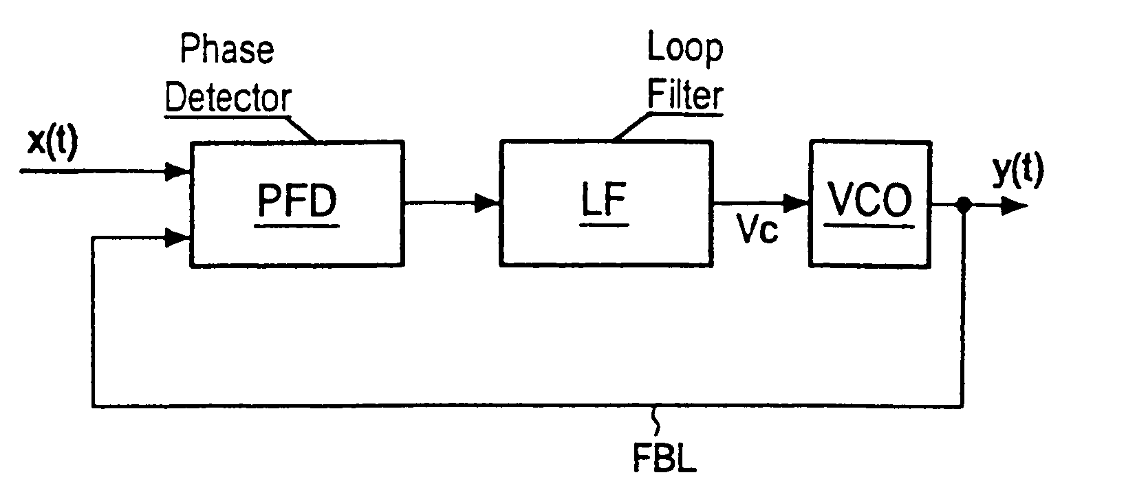
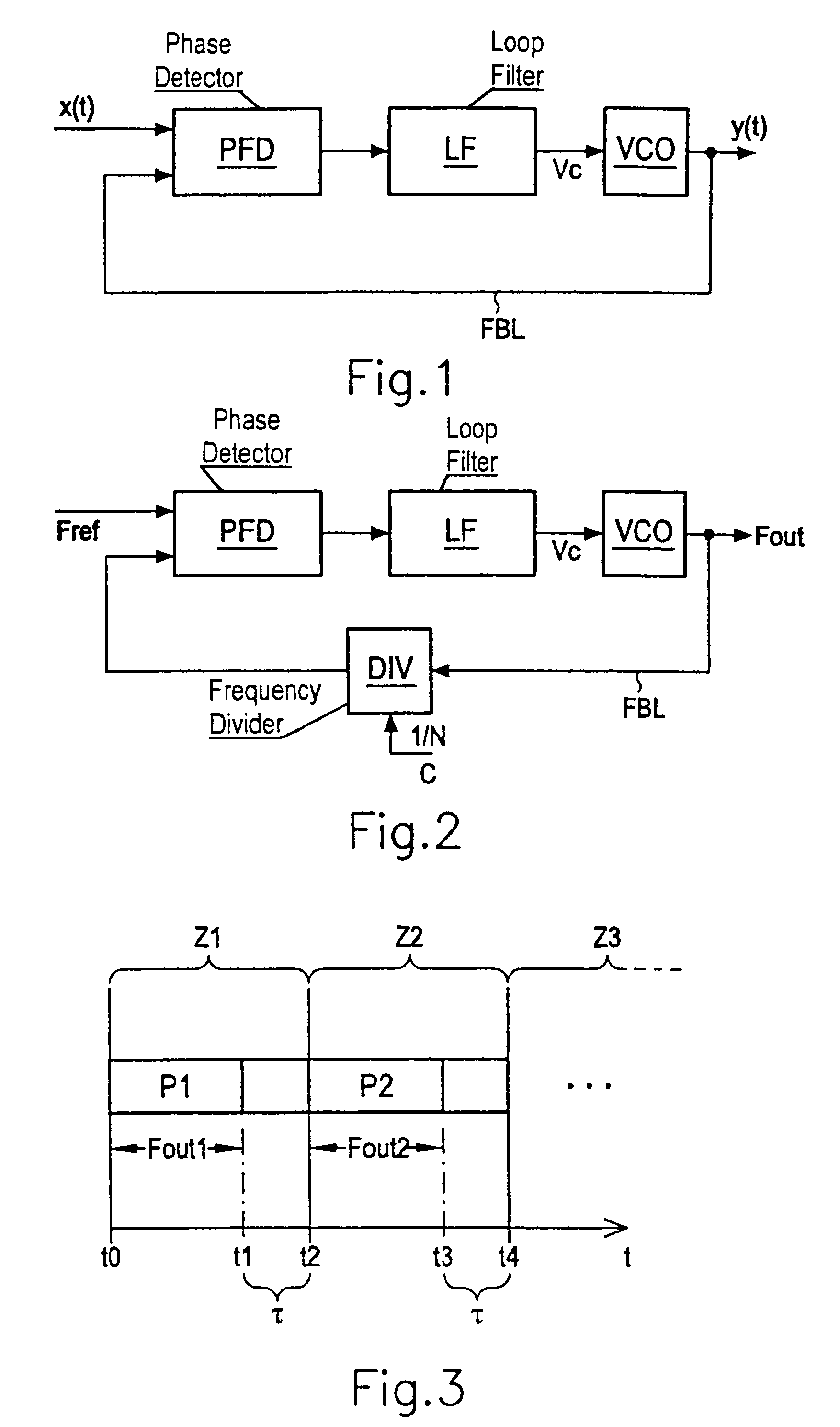
[0024]Referring now to the figures of the drawing in detail and first, particularly, to FIG. 1 thereof, there is shown a basic configuration of a PLL circuit. The PLL circuit has a phase detector PFD (Phase Frequency Detector), a loop filter LF and a voltage controlled oscillator VCO. The VCO produces a periodic oscillation y(t) which is fed back via a feedback line FBL (Feedback Loop) to a first input of the phase detector PFD. A second input of the phase detector PFD is supplied with a reference variable x(t) in the form of an oscillation. A variable t denotes the time.
[0025]The object of the PLL circuit is to allow the time response of the output variable y(t) to follow the input variable x(t). In other words, the frequency of the voltage controlled oscillator VCO should be set such that it matches the frequency of the oscillation x(t). To do this, the phase of the output signal y(t) is compared with the phase of the reference variable x(t). The phase detector PFD outputs an outp...
PUM
 Abstract
Description
Claims
Application Information
 - R&D
- Intellectual Property
- Life Sciences
- Materials
- Tech Scout
- Unparalleled Data Quality
- Higher Quality Content
- 60% Fewer Hallucinations
Browse by: Latest US Patents, China's latest patents, Technical Efficacy Thesaurus, Application Domain, Technology Topic, Popular Technical Reports.
© 2025 PatSnap. All rights reserved.Legal|Privacy policy|Modern Slavery Act Transparency Statement|Sitemap|About US| Contact US: help@patsnap.com


