
Method and apparatus for making snow

a technology of snowmaking and snowmaking, applied in the field of snowmaking, can solve the problems of unsatisfactory skiing conditions, ice or snow particles, etc., and achieve the effects of enhancing safety, reducing torque or effort, and reliable leakproof operation

Inactive Publication Date: 2007-11-06
SNOW MACHINES
View PDF252 Cites 20 Cited by
  • Summary
  • Abstract
  • Description
  • Claims
  • Application Information

AI Technical Summary

Benefits of technology

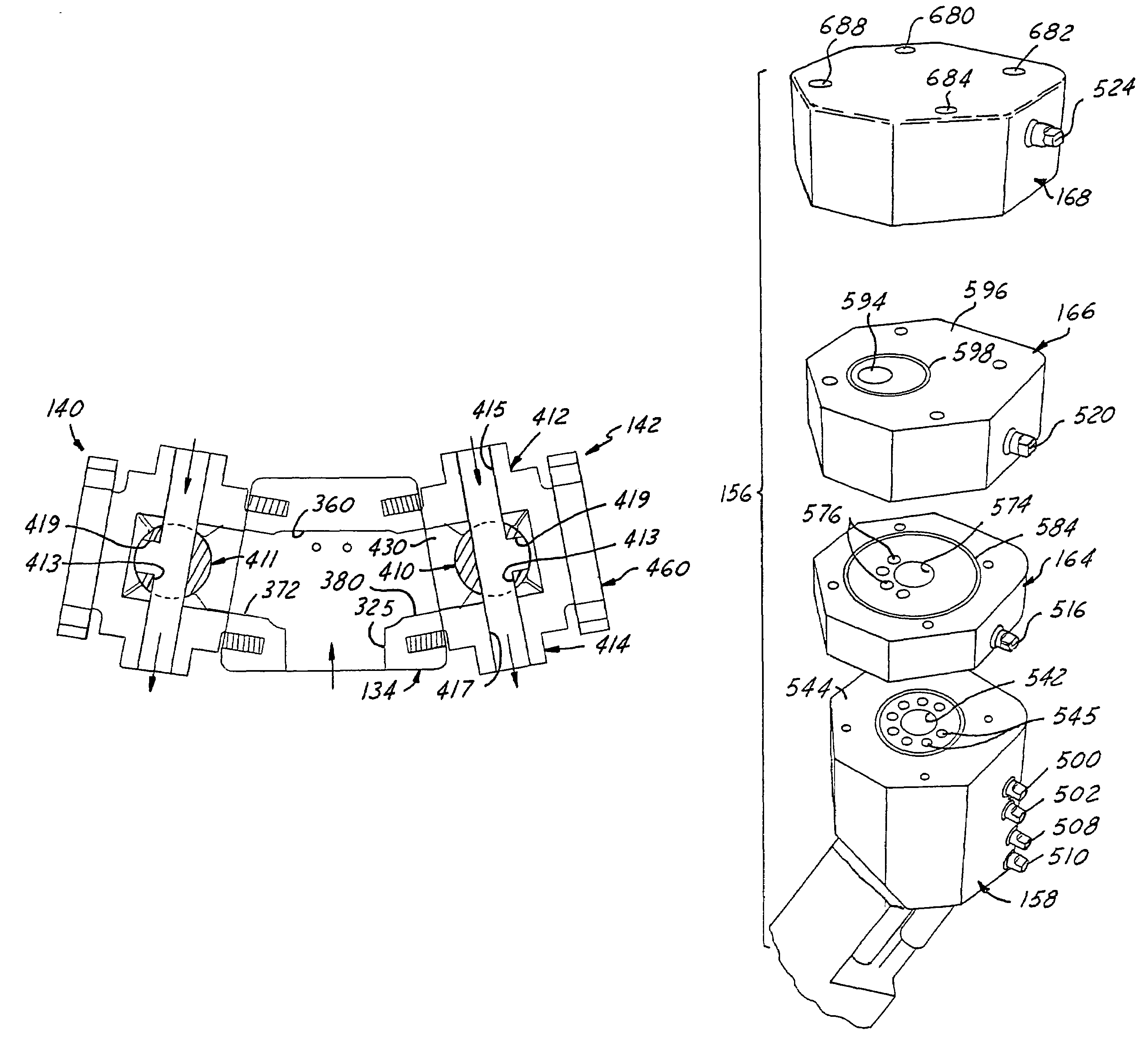
[0008]Among one or more of the objects of the invention is to provide an improved snow making tower wherein (1) primary water is fed in a novel manner into a water feed block and up into the tower pipe sleeve and then to feed spray head, and cooperative improved secondary and tertiary water supply valves that ensure that turbulent water continuously flows in such a manner that heaters are not needed and yet such valves do not freeze up;
[0009](2) an improved hydraulic jack and safety latch system to provide a compact hoisting apparatus with much mechanical advantage, and enabling the boom to be easily and safely positioned at any angular position in its range of pivotal travel established by jack operation, and yet ensures that the entire boom may safely retropivot back downwardly a very short distance established by a latch system that can be quickly converted over to a nonlatching mode to allow the boom to be dropped as rapidly as desired under the operator control of the hydraulic release valve on the ram;
[0010](3) a modular design spray head enabling manufacturing economies to be achieved and facilitating cleaning, repair and replacement in the field;

Problems solved by technology

In connection with the atomizing of water for snow making it has long been known that the water particle size should be as small as possible, in many cases as small as 200 microns or less, because if such particles are too large, depending on ambient weather conditions and the ratio of water to air mixture, they will produce ice or sleet particles which are unsatisfactory for desirable skiing conditions.

Method used


Image

  • Method and apparatus for making snow
  • Method and apparatus for making snow
  • Method and apparatus for making snow

Examples


Embodiment Construction

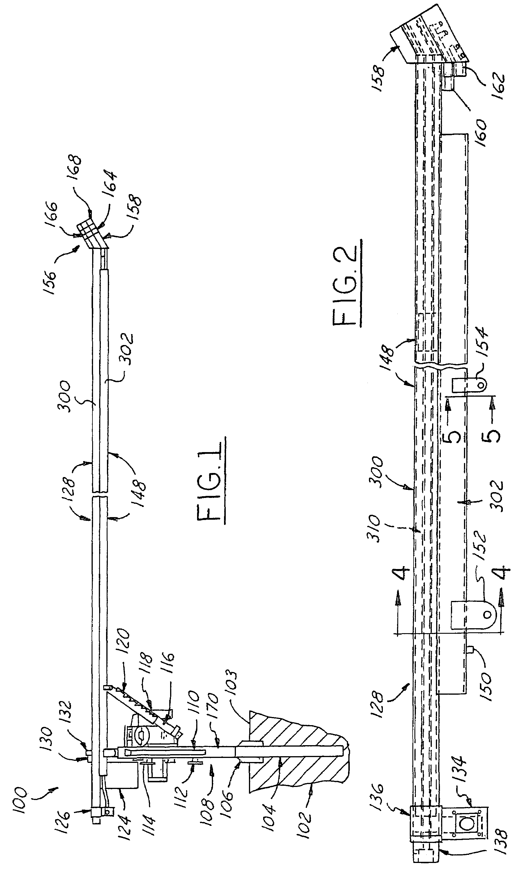
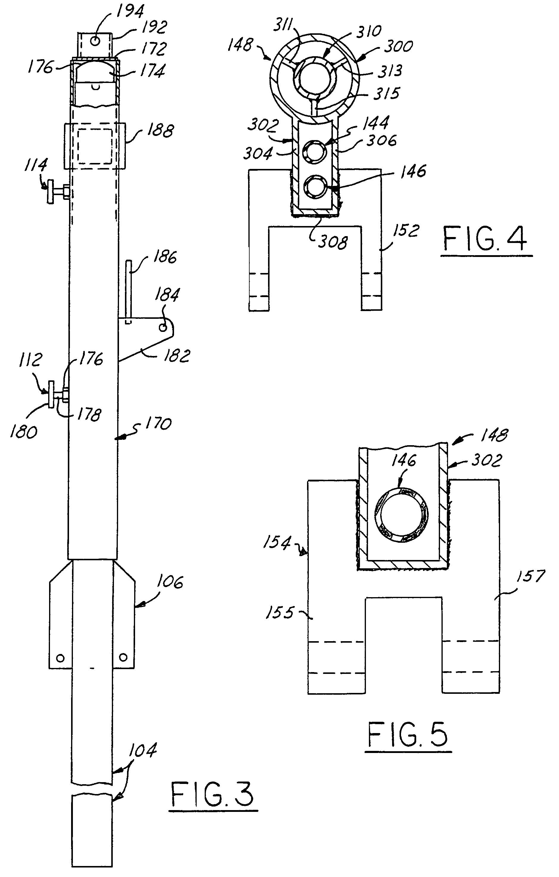
[0080]Referring in more detail to the accompanying drawings, FIG. 1 illustrates in a somewhat simplified format the overall construction and assembly of an exemplary but presently preferred first embodiment of an adjustable snow making tower 100 of the present invention. Referring to FIG. 1, as well as to FIGS. 2-8, the principal components of tower 100 are identified by reference numerals as follows:[0081]100—overall adjustable snow making tower[0082]102—support pole foundation[0083]103—surface of foundation material (e.g., concrete, rock or earthen-material)[0084]104—support pole[0085]106—support pole anti-rotation and stiffening fins[0086]108—tower pipe assembly[0087]110—tower turning handle[0088]112—lower service lock[0089]114—upper service lock[0090]116—hydraulic jack[0091]118—on-board electric motorair compressor assembly[0092]120—hydraulic jack safety latch[0093]122—hydraulic jack stop assembly[0094]124—electrical control panel[0095]126—compressed air feed hose[0096]126—wate...


PUM


Abstract

An elongated pipe conduit snow making tower, and assembly method, having an upper end spray nozzle head and pivotally supported on a support pipe for vertical inclination by a hydraulic ram jack enabling infinite non-preselected incremental inclinations. A ram safety latch automatically latch / catches the tower pipe if the jack leaks. Secondary and tertiary external flexible water hoses are selectable to feed associated spray head snowmaking nozzles, and an internal compressed air conduit feeds spray head seeding nozzles. Secondary and tertiary ball valve assemblies mounted on a water feed block are outlet coupled to their respective hoses. In drain condition turbulent primary water continually washes against a valve ball flow closure side for an anti-freezing effect. The spray head is a four-piece modular planar stack up of disks each carrying spray nozzles that all discharge forwardly away from the pipe tower in generally parallel spray patterns.

Description

[0001]This is a United States regular utility patent application filed pursuant to 35 U.S.C. § 111(a) and claiming the benefit under 35 U.S.C. § 119(e)(1) of the priority U.S. provisional application Ser. No. 60 / 529,935 filed Dec. 16, 2003.TECHNICAL FIELD[0002]The present invention relates generally to the art of snow making and an improved method and apparatus for making large volumes of high quality artificial snow suitable for skiing, and more particularly to universally adjustable tower-type snowmakers for ski slopes.BACKGROUND OF THE INVENTION[0003]Numerous water spray systems have been developed for producing snow wherein water and air under pressure are in some manner mixed and commingled. The principle involved is to reduce the size of water particles to the smallest size possible, typically by high pressure discharge of water through an atomizing nozzle orifice to form a spray, and augmented by injection of compressed air directly or indirectly with the water spray or mixin...

Claims


Application Information

Patent Timeline
IPC IPC(8): A01G15/00
CPCF25C3/04F25C2303/0481
Inventor EWALD, JEFFREY ALLEN
Owner SNOW MACHINES
Learn More