Image encoder, image decoder, image encoding method, and image decoding method

a technology of image encoder and encoder, which is applied in the direction of color television with bandwidth reduction, television system, instruments, etc., can solve the problem of insufficient efficiency of arithmetic coding and achieve the effect of improving the efficiency of entropy coding of the basis coefficient data

Inactive Publication Date: 2007-11-06
NTT DOCOMO INC
View PDF10 Cites 37 Cited by
  • Summary
  • Abstract
  • Description
  • Claims
  • Application Information

AI Technical Summary

Benefits of technology

[0038]The basis coefficient data used in the representation of unit elements of prediction residual data in predetermined partial image regions is largely dependent on the detection order of prediction residual data in these predetermined partial image regions. Therefore, by determining the frequency of occurrence distribution of the basis coefficient data of the

Problems solved by technology

As a result, the efficiency of the arithmetic coding cannot be adequately produced

Method used


Image

  • Image encoder, image decoder, image encoding method, and image decoding method
  • Image encoder, image decoder, image encoding method, and image decoding method
  • Image encoder, image decoder, image encoding method, and image decoding method

Examples


first embodiment

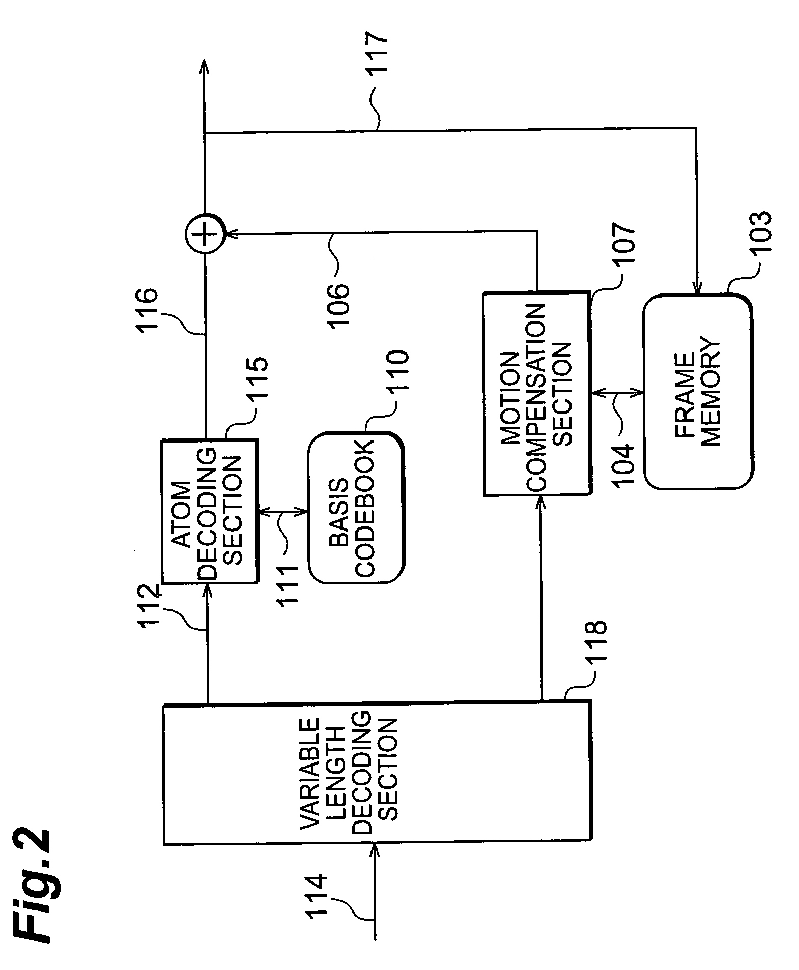
[0064]The image coding apparatus and decoding apparatus according to the first embodiment have an image signal comprising an array of image frames inputted thereto and are mainly constituted by: a coding apparatus constituted by interframe motion compensation predicting means; coding mode selecting means and texture signal compression / coding means; and a decoding apparatus for decording the image signal upon receiving compressed image data (referred to as a ‘bit stream’ hereinafter) generated by the coding apparatus.

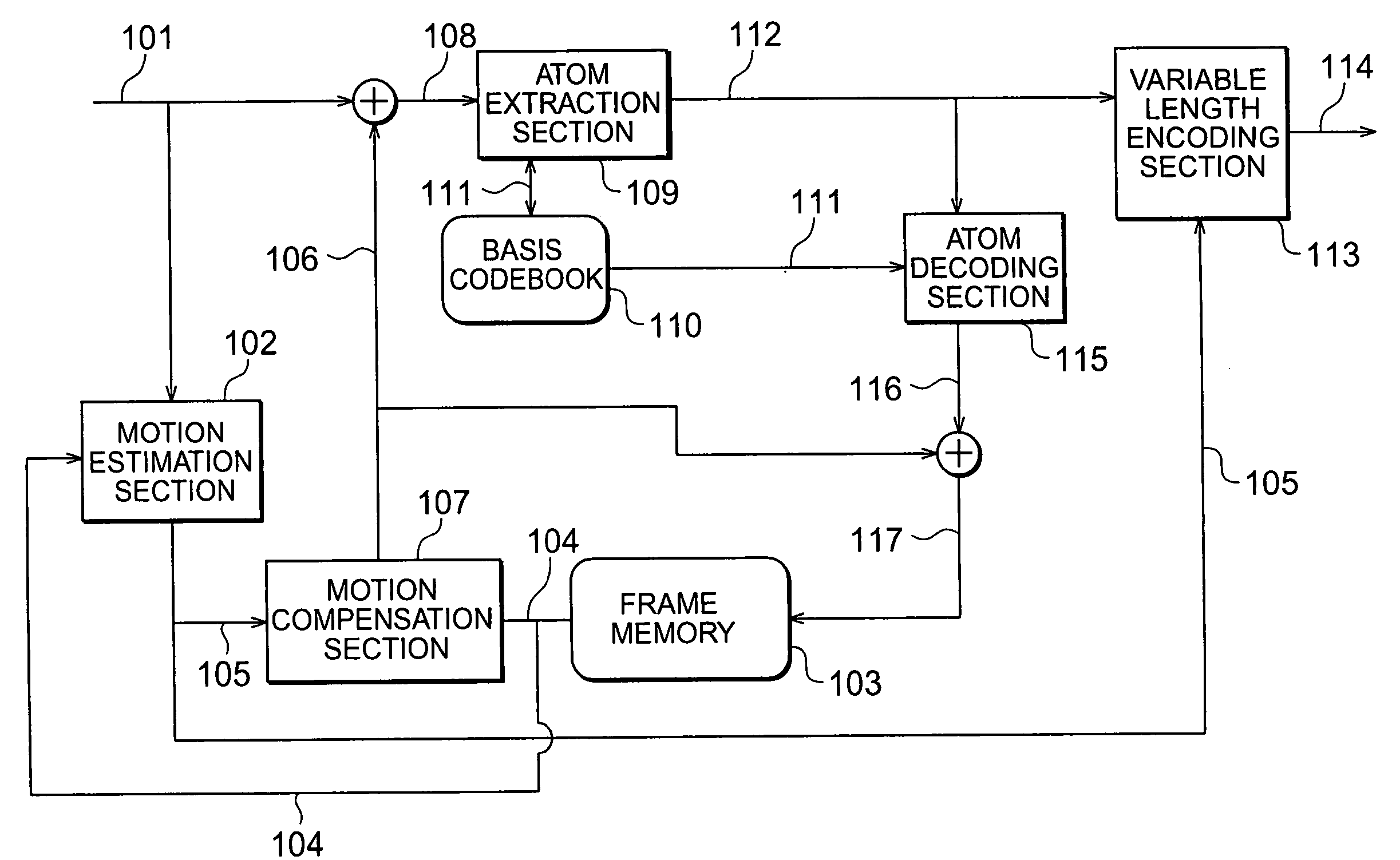
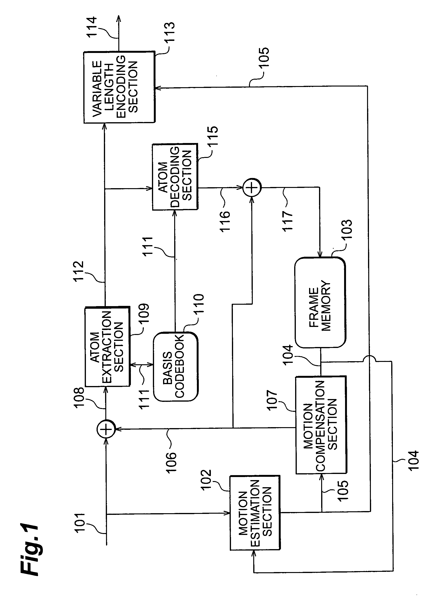
[0065]Referring now to FIG. 1, a description will now be provided for the image coding apparatus according to the first embodiment. An input image signal 101 is a temporal array of frame images and embodies the frame image unit signals hereinbelow. A frame is divided into fixed square / rectangular regions of 16 pixels×16 lines (referred to as ‘macroblocks’ below), the processing detailed below being performed using such units. In other words, the macroblock data of the in...

second embodiment

[0148]In the second embodiment, a description is provided for an apparatus for coding / decoding atom parameters in frame units, rather than in the macroblock units employed by the coding / decoding apparatus according to the first embodiment. FIG. 10 shows the coding data array (syntax) aspect of a frame unit of the compressed stream 114. Following on from the frame header which stores the frame time stamp, initial parameters, activity data (details provided hereinafter), and so forth, data relating to the motion, in fixed block units, of macroblocks such as those described in the first embodiment is combined and multiplexed, for example. Here, a counter N is the number of macroblocks in the frame and is generally a constant that is determined uniquely for the image size. A sync word is inserted next. The sync word is required to be a unique code indicating the start of the atom parameters for this frame. The insertion of the sync word enables the decoding apparatus to separate in adva...


PUM


Abstract

The image coding apparatus is constituted comprising an atom extraction section 109 for acquiring position data indicating the positions of atoms of prediction residual data in macroblocks, for each of the macroblocks; and a variable length encoding section 113 for determining the frequency of occurrence distribution of the position data in the macroblocks to be encoded, in accordance with the number of atoms of prediction residual data present in the macroblocks, and for performing arithmetic coding of the position data on the basis of the frequency of occurrence distribution thus determined. An improvement in the efficiency of the entropy coding of the atom parameters of Matching Pursuits coding is therefore feasible.

Description

TECHNICAL FIELD[0001]The present invention relates to an image coding apparatus, an image decoding apparatus, an image coding method, and an image decoding method that permit the transmission and storage of images with a small encoded volume.BACKGROUND ART[0002]Standard moving image coding systems such as ITU-T H. 26x and the MPEG series are known from the prior art. In these standard moving image coding systems, from the viewpoint of the balance between compression efficiency and load, and indeed of the popularization of dedicated LSI, the Discrete cosine transform (referred to as “DCT” hereinbelow) is mainly employed. However, due to the fact that the DCT performs basis coefficient quantization, in cases where encoding is performed at a very low bit rate, the basis, which is key as far as the representation of the original signal is concerned, cannot be restored and, as a result, there is the problem that distortion is generated. As methods for resolving such problems, Matching Pu...

Claims


Application Information

Patent Timeline
IPC IPC(8): G06K9/36G06K9/46H04N19/11G06T9/00H04N19/00H04N19/13H04N19/36H04N19/50H04N19/503H04N19/51H04N19/593H04N19/61H04N19/625H04N19/90H04N19/91H04N19/94H04N19/97
CPCH04N19/56H04N19/97H04N19/52H04N19/503H04N19/139H04N19/176H04N19/70H04N19/46H04N19/51H04N19/61H04N19/593H04N19/91H04N19/136H04N19/14H04N19/137H04N19/17H04N19/184H04N19/105
Inventor SEKIGUCHI, SHUNICHIKINNO, AKIRASUGIMOTO, KAZUOETOH, MINORU
Owner NTT DOCOMO INC
Why Eureka
Try Eureka