Multi-beam laser communications system and method

a laser communication and multi-beam technology, applied in electromagnetic transmission, electrical equipment, transmission, etc., can solve problems such as limited performance, and achieve the effect of large angle retargeting between laser communication channels and rapid respons

Active Publication Date: 2007-11-06
LOCKHEED MARTIN CORP
View PDF18 Cites 25 Cited by
  • Summary
  • Abstract
  • Description
  • Claims
  • Application Information

AI Technical Summary

Benefits of technology

[0006]According to one aspect of the present invention, acquisition and tracking of multiple independently targeted laser communications devices from a...

Problems solved by technology

As an example, rapid retargeting with current technology allows switching between two different laser communications ...

Method used


Image

  • Multi-beam laser communications system and method
  • Multi-beam laser communications system and method
  • Multi-beam laser communications system and method

Examples


Embodiment Construction

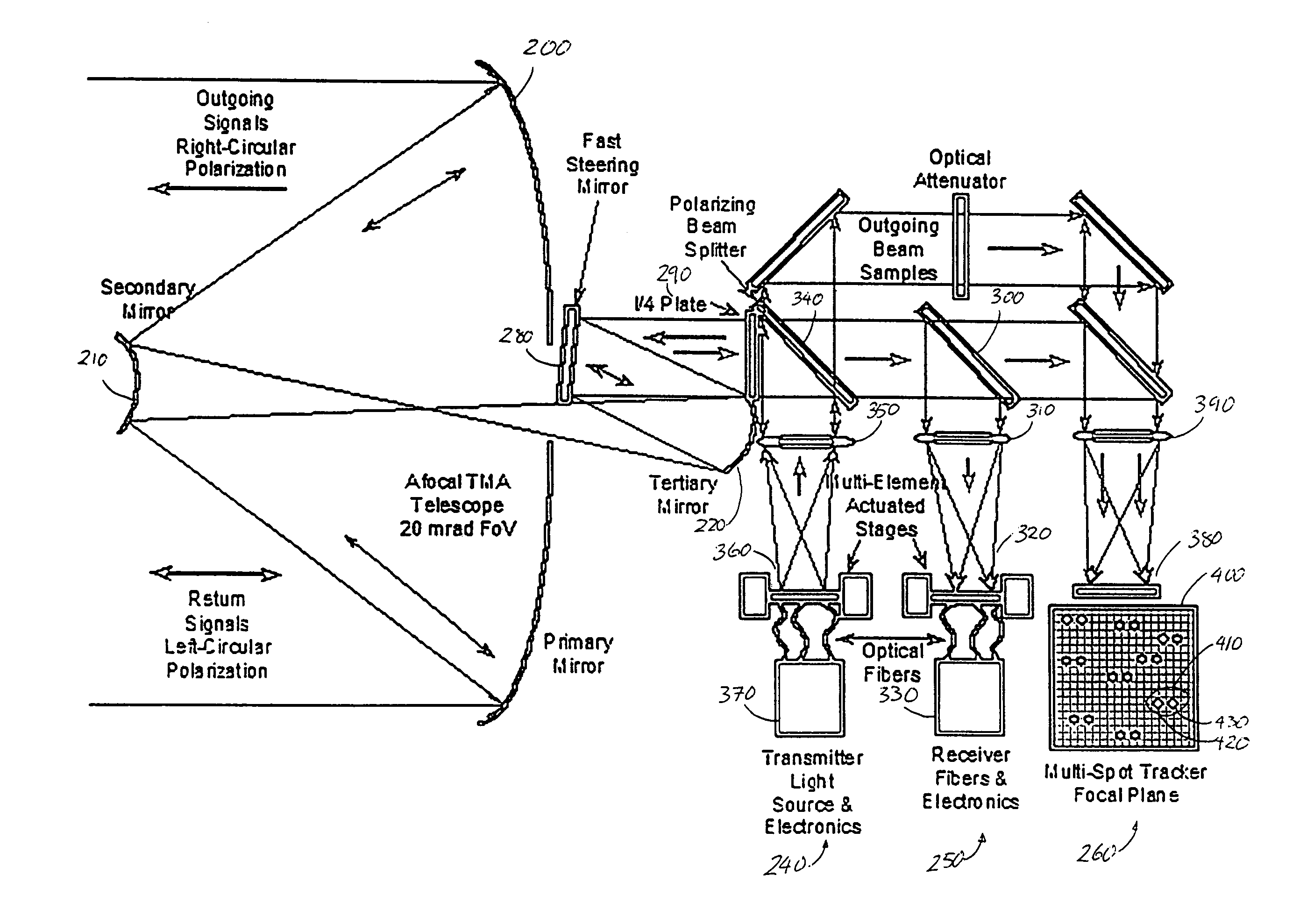
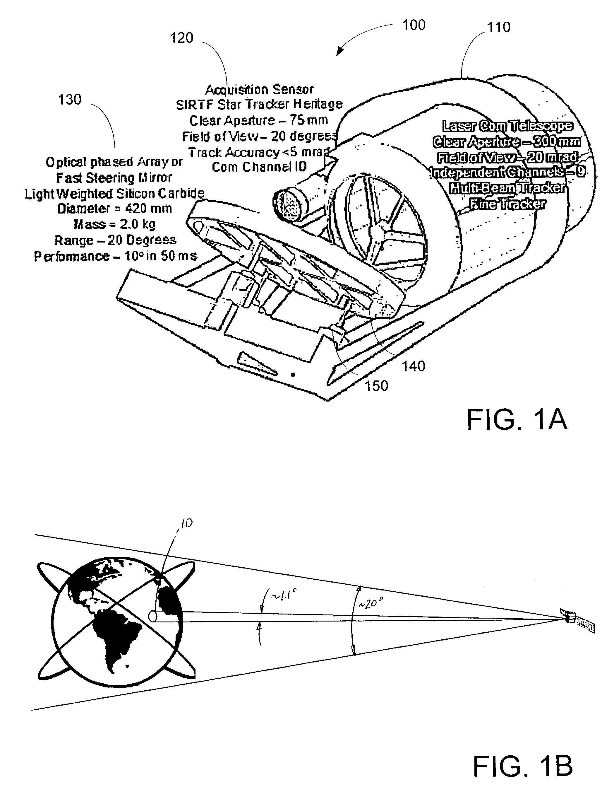
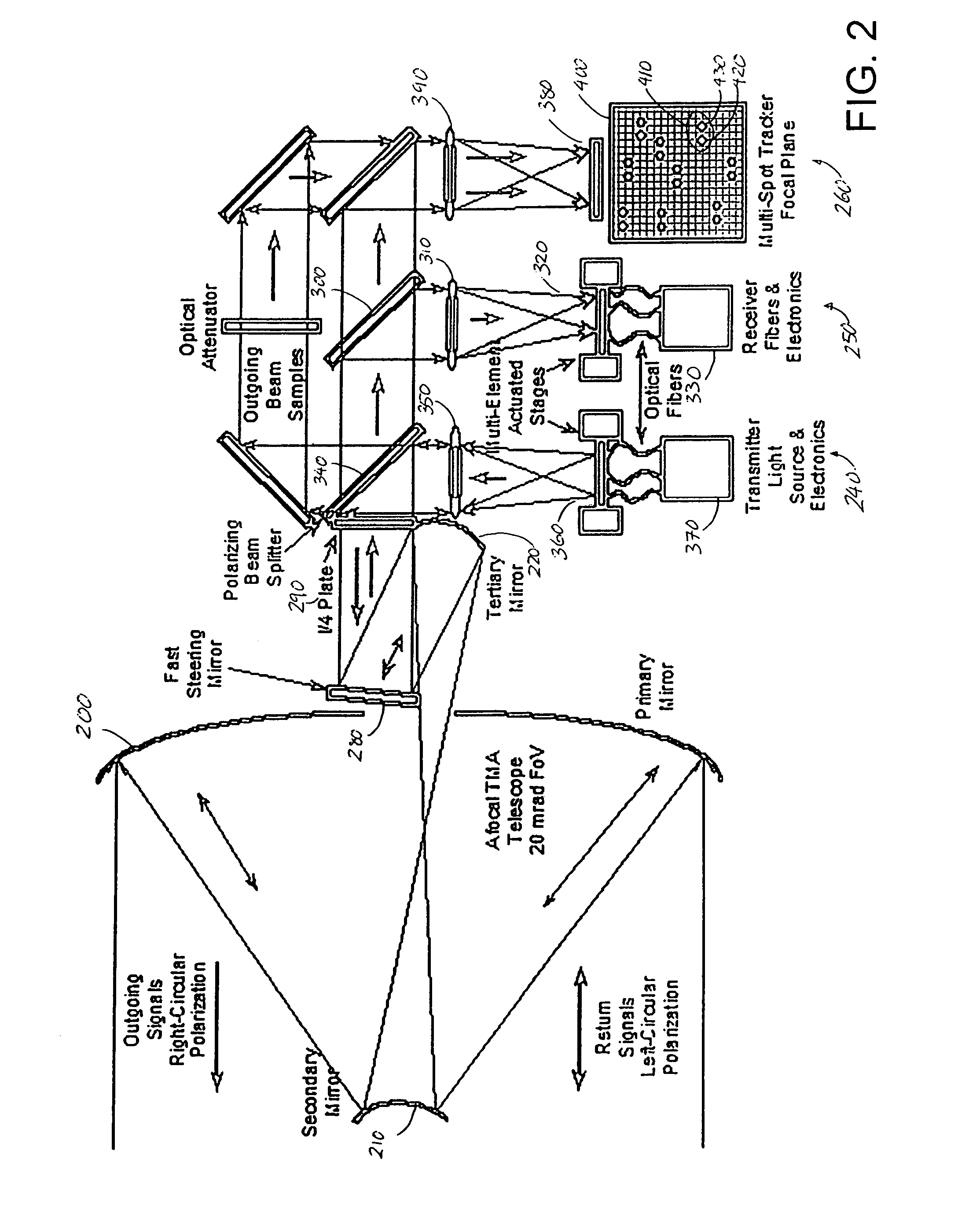
[0022]FIGS. 1A and B illustrate an embodiment of the present invention. In particular, FIG. 1A illustrates three portions of a laser communications platform 100. Platform 100 includes an optical system (a laser communications projector / receiver telescope) PRT 110, an acquisition tracker system (AT) 120, and a fast steering mirror (FSM). FIG. 1B illustrates a field of view of an embodiment of the present invention.

[0023]In embodiments of the present invention, platform 100 will be a space based communications platform located in geostationary or geosynchronous (GEO) orbit around the earth at an altitude of approximately 35,800 km. In other embodiments, platform 100 may have different orbits, fields of view, specifications, and the like.

[0024]As illustrated in FIG. 1B, in one embodiment of the present invention AT 120 is a laser communications tracking system with a field of view of approximately 20°. In other embodiments of the present invention, the field of view is greater than app...


PUM


Abstract

A laser communications system includes a wide-field sensor, configured to detect a first set of laser communications sources within a first field of view, a narrow-field sensor includes a tracking portion and a control portion configured to receive laser communications from a second set of laser communications sources within a second field of view, wherein the first field of view is larger than the second field of view, and wherein the second set of laser communications sources comprises at least a first source and a second source, and a redirection unit coupled to the narrow-field sensor configured to position the second field of view within the first field of view wherein the first receiving element is positioned in response to the first positioning signal for the first receiving element, and the second receiving element is positioned in response to the first positioning signal for the second receiving element.

Description

BACKGROUND OF THE INVENTION[0001]Communications via satellites, that forty years ago was novel, has now become common. Whether the communications are telephone calls, the latest video for the 10 O'clock news, or surfing the web, etc., the concept of sending a signal to a satellite, and having the satellite rebroadcast the signal is well established. Typical state of the art satellites broadcast signals in the range of 3-30 Gigahertz, with corresponding data rates of up to 20 Mbits / second.[0002]Although this data rate may sound impressive at first, the inventors of the present invention have contemplated that in the future, a substantially higher data satellite rates will be required. For example, the inventors contemplate that satellite data rates in the order of Terahertz may be necessary.[0003]One method contemplated by the inventors for increasing the data bandwidth is to increase the number of communications satellites. Drawbacks to this approach include that communications sate...

Claims


Application Information

Patent Timeline
IPC IPC(8): H04B10/00H04B10/10
CPCH04B10/1125
Inventor TRIEBES, KENNETH J.ENOCH, MICHAELCAPOTS, LARRY H.
Owner LOCKHEED MARTIN CORP
Why Eureka
Try Eureka