Retransmission scheme in a cellular communication system

retransmission scheme technology, applied in the field of retransmission scheme in a cellular communication system, can solve the problems of increasing other delays, affecting the operation of the system, and the performance is not optimal, so as to facilitate the target parameter being determined, facilitate operation, and facilitate operation

Active Publication Date: 2007-11-06
SONY CORP
View PDF12 Cites 41 Cited by
  • Summary
  • Abstract
  • Description
  • Claims
  • Application Information

AI Technical Summary

Benefits of technology

[0026]The invention may provide for an improved performance of a cellular communication system. In particular, the invention may allow an improved performance wherein an operating point of a retransmission scheme may be adapted to the current characteristics of the cellular communication system. The invention may allow a trade off between resource usage and delay to be dynamically adjusted and / or may allow an improved trade off between queuing delays and retransmission delays. For example, at low loads, the transmission parameter may be set to result in a high resource usage per transmitted information bit but low probability of retransmissions thereby reducing retransmission delays whereas at high loads, the transmission parameter may be set to result in a low resource usage per transmitted information bit but at a higher probability of retransmissions thereby reducing the queuing delay and increasing capacity. In some embodiments, the latency associated with communication of data may be reduced or minimised.
[0060]According to an optional feature of the invention, the retransmission scheme is a Hybrid Automatic Repeat reQuest (H-ARQ) scheme. The invention may provide improved performance for an H-ARQ retransmission scheme. In particular, the soft combining of transmissions may be used to increase capacity and reduce queuing delays for high loadings whereas a more robust communication may be used at lower loadings to reduce retransmission delays.

Problems solved by technology

However, despite these techniques, the performance is not optimal.
Although such an operating point may provide acceptable performance in general, it is not optimal for many situations and may in particular result in a relatively high latency.
For example, although an increased capacity may reduce queuing delays, it may also increase other delays such as the delay associated with retransmissions.
Therefore, in order to achieve a sufficiently high capacity, the retransmission delays may frequently result in a latency which is higher than desired.
However, this results in an increased block error rate and thus an increased number of retransmissions being required for successful communication.
As the delay before a retransmission occurs is substantial, this may substantially increase the resulting average delay of transmitting data packets.

Method used


Image

  • Retransmission scheme in a cellular communication system
  • Retransmission scheme in a cellular communication system
  • Retransmission scheme in a cellular communication system

Examples


Embodiment Construction

[0085]The following description focuses on an embodiment of the invention applicable to a UMTS cellular communication system and in particular to an application for a HSDPA or HSUPA service. However, it will be appreciated that the invention is not limited to this application but may be applied to many other cellular communication systems and / or services.

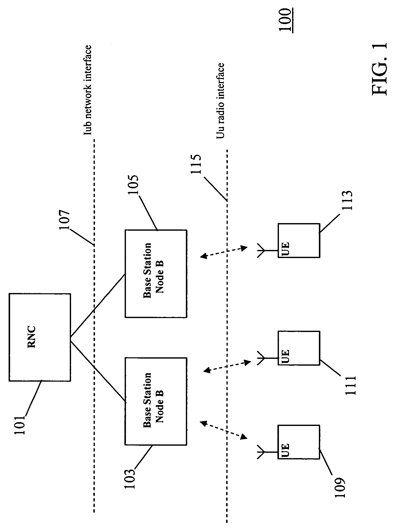
[0086]FIG. 1 is an illustration of part of a UMTS cellular communication system 100 in accordance with embodiments of the invention.

[0087]FIG. 1 illustrates a Radio Network Controller (RNC) 101 which is connected to two base stations 103, 105 which are known as Node Bs in a UMTS cellular communication system. The interface between the RNC 101 and the base stations 103, 105 are known as the Iub interface 107. The base stations 103, 105 support a number of remote units 109, 111, 113 (or user equipment). For clarity and brevity, FIG. 1 illustrates two remote units 109, 111 being supported by the first base station 103 and one remote un...


PUM


Abstract

An apparatus 300 for a cellular communication system (100) comprises a buffer (303) which receives data for transmission over an air interface (115). The buffer (303) is coupled to a scheduler (305) which schedules the data and allocates the physical resource of the air interface (115). The transmissions are performed using a retransmission scheme such as a Hybrid-Automatic Repeat reQuest scheme. A load processor (309) determines a load characteristic associated with the scheduler (305) and a target controller (311) sets a target parameter for the retransmission scheme in response to the load characteristic. Specifically, a block error rate target may be set in response to a load level of a cell or plurality of cells. A transmission controller (307) sets a transmission parameter for a transmission in response to the target parameter and a transmitter (301) transmits the data using the transmission parameter. Accordingly, an operating point of the retransmission scheme may be dynamically adjusted thereby reducing overall latency.

Description

FIELD OF THE INVENTION[0001]The invention relates to an apparatus, a base station and a method for controlling at least one transmission of a retransmission scheme in a cellular communication system.BACKGROUND OF THE INVENTION[0002]In a cellular communication system, a geographical region is divided into a number of cells each of which is served by base stations. The base stations are interconnected by a fixed network which can communicate data between the base stations. A mobile station is served via a radio communication link from the base station of the cell within which the mobile station is situated.[0003]A typical cellular communication system extends coverage over an entire country and comprises hundreds or even thousands of cells supporting thousands or even millions of mobile stations. Communication from a mobile station to a base station is known as the uplink, and communication from a base station to a mobile station is known as the downlink.[0004]The fixed network interc...

Claims


Application Information

Patent Timeline
Patent Type & Authority Patents(United States)
IPC IPC(8): H04B17/00H04W24/00H04W28/04H04W28/14H04W52/34H04W72/04H04W72/12H04W84/04
CPCH04L1/1887H04L47/14H04L1/0021H04W52/34H04L1/0003H04L1/0009H04L1/1812H04W28/04H04W28/14H04W72/0486H04W84/042H04W24/00H04W28/02H04W72/52H04W8/04
Inventor BEALE, MARTIN W.ANDERSON, NICHOLAS W.
Owner SONY CORP
Why Eureka
Try Eureka