Exposure apparatus, cooling method, and device manufacturing method

a technology of cooling technology and equipment, applied in the field of cooling technology for optical components, can solve the problems of reducing the accuracy of the transfer position, affecting the accuracy of the temperature control, and limiting the enlargement of the surface area of opposed surfaces, so as to achieve the effect of improving the accuracy of temperature control due to the delay of control

Inactive Publication Date: 2007-11-13
CANON KK
View PDF12 Cites 2 Cited by
  • Summary
  • Abstract
  • Description
  • Claims
  • Application Information

AI Technical Summary

Benefits of technology

[0011]It is accordingly an object of the present invention to provide an exposure apparatus, a cooling method and / or a device manufacturing method, by which degradation of temperature control precision due to a delay of control can be improved such that temperature variation can be held within a tolerable range.

Problems solved by technology

Use of EUV as a light source necessitates exposure in a vacuum ambience, and this makes it difficult to accomplish temperature adjustment.
Furthermore, the temperature adjustment based on flow of a cooling medium will cause vibration, which undesirably leads to degradation of the transfer positional precision.
However, there is a limitation to enlargement of the surface area of opposed surfaces and, for this reason, it becomes very important to produce a large surface temperature difference between the two objects.
It is therefore necessary to improve degradation of the control precision resulting from such control delay.
This means that the mirror has a large heat capacity, such that there occurs a time lag until a temperature sensor can detect application of heat as a temperature rise.
This causes a delay of control and degradation of control precision.

Method used


Image

  • Exposure apparatus, cooling method, and device manufacturing method
  • Exposure apparatus, cooling method, and device manufacturing method
  • Exposure apparatus, cooling method, and device manufacturing method

Examples


first embodiment

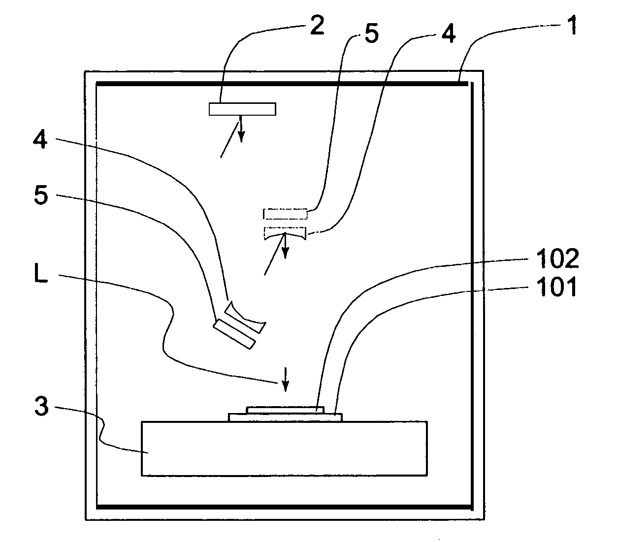
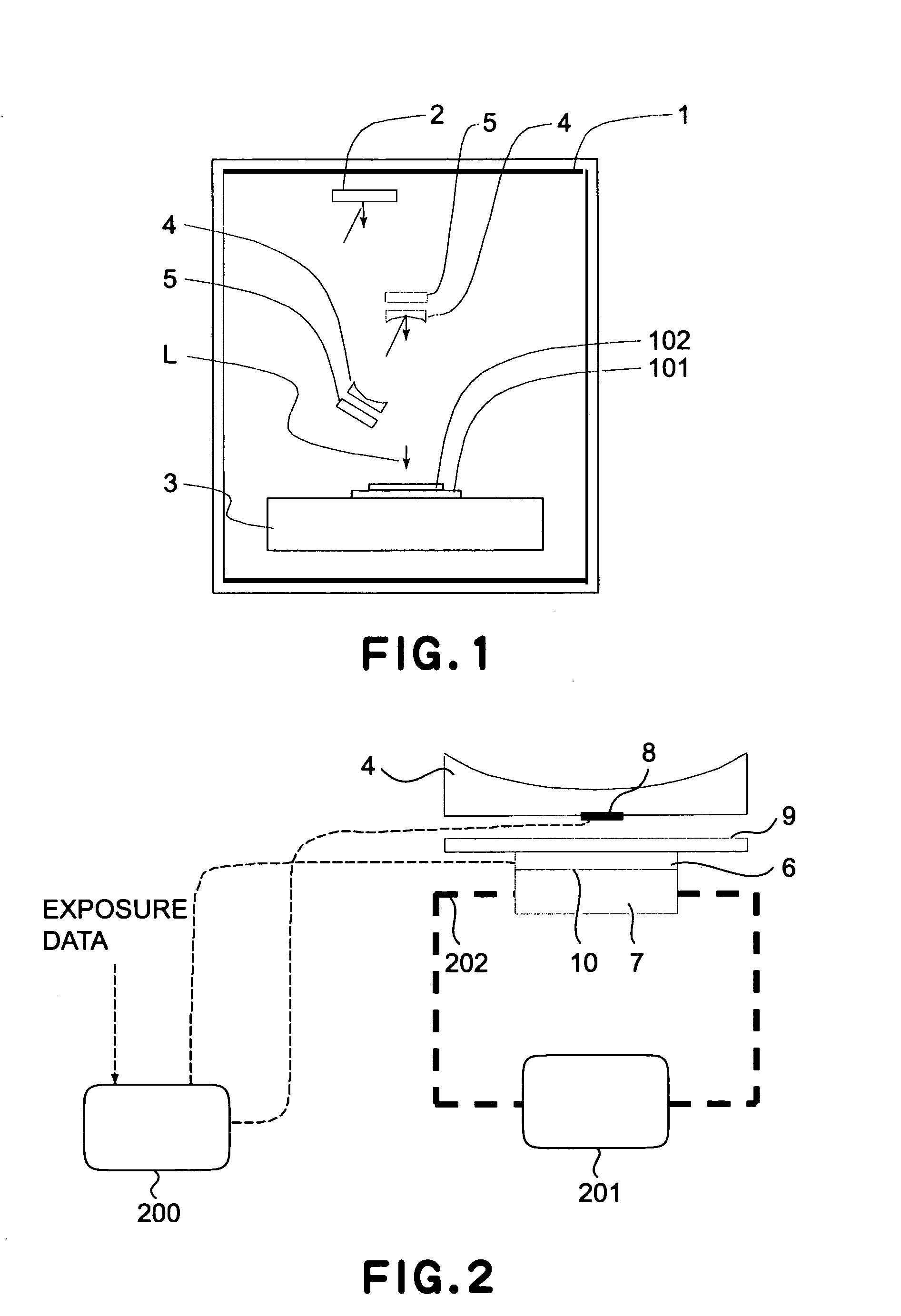
[0025]FIG. 1 is a schematic view for explaining an example of exposure apparatus based on a cooling method, according to a first embodiment of the present invention. Denoted at 1 is a chamber which functions to separate an exposure ambience from an atmosphere. A vacuum is maintained in the chamber, by means of a pump, not shown. Exposure light L directed from an unshown illumination optical system is reflected by a reticle 2. The exposure light L as reflected by the reticle 2 is reflected by mirrors of a projection optical system and projected upon a wafer 102, whereby a pattern of the reticle 2 is transferred to the wafer 102. Wafer 102 is in a wafer chuck 101 mounted on a block 3. There is a radiation cooling mechanism 5 disposed opposed to the bottom face of the mirror 4.

[0026]FIG. 2 is a schematic view of the radiation cooling mechanism. The radiation cooling mechanism 5 comprises a Peltier device 6, a heat radiating (dissipation) block 7, and a radiation plate 9. The Peltier el...

second embodiment

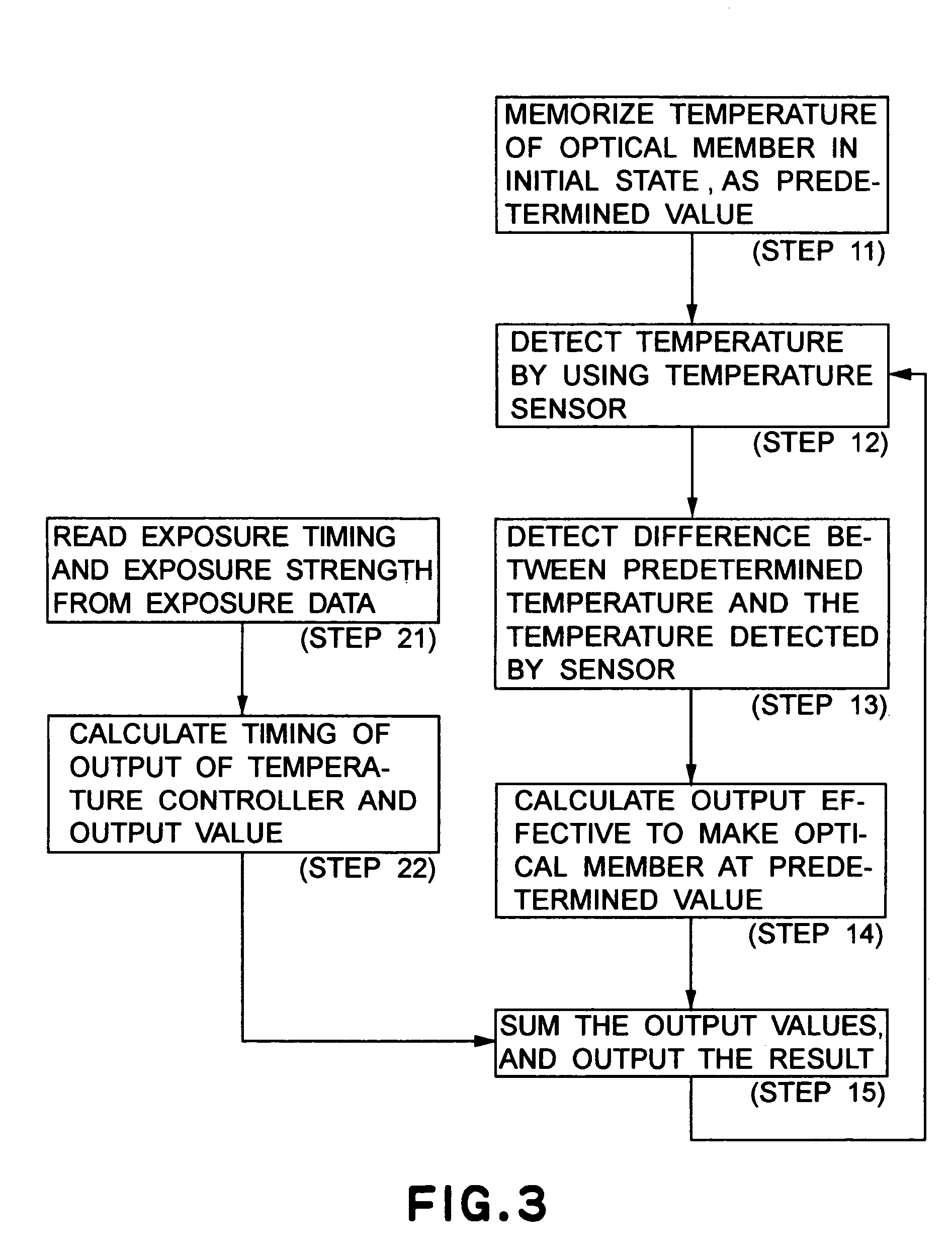
[0045]A second embodiment of the present invention concerns a cooling method wherein every mirror is cooled in accordance with the procedure shown in FIG. 3. More specifically, as shown in FIG. 6, mirrors may have different shapes. Also, heat loads applied to the mirrors may be different from each other. Thus, the timing for changing the temperature of the radiation plate 9 to be calculated by step 22 may differ between the mirrors. In consideration of it, in accordance with the present embodiment, with respect to each of plural mirrors, a function or a table that represents the output timing and the output level to heat loads, to be used at step 22, is prepared. With this arrangement, a signal can be applied at an optimum timing in relation to each mirror. Thus, in regard to all the mirrors, the temperature can be controlled with good precision, within a tolerable temperature variation range.

[0046]While the foregoing embodiments have been described specifically with respect to a co...

third embodiment

[0048]A third embodiment of the present invention is directed to a cooling method wherein the present invention is applied to a process for cooling a wafer chuck, not a mirror, as shown in FIG. 7.

[0049]Denoted in FIG. 7 at 102 is a wafer, and denoted at 101 is a wafer chuck. Denoted at 9 is a radiation cooling plate, and denoted at 6 is a Peltier device. Since any thermal deformation of the wafer chuck 101 directly leads to deformation of a wafer 102, it is very important for improvements of pattern transfer precision of an exposure apparatus to suppress temperature variation of the wafer chuck 101. The wafer chuck 101 is made of a material having a high specific rigidity, such as SiC, for example, so as to suppress deformation due to any external force.

[0050]Here, for better performance of a wafer stage (lightness or rigidity, for example), the material of the wafer chuck should desirably have a specific rigidity of 1E+8 (N·m / kg) or more.

[0051]Further, in order that the wafer chuck...


PUM

PropertyMeasurementUnit
temperatureaaaaaaaaaa
diameteraaaaaaaaaa

Abstract

Disclosed herein are an exposure apparatus and a cooling method usable therein, being effective to improve a mirror temperature-control precision and to suppress temperature changes in a certain allowable range, particularly in an EUV exposure apparatus. The exposure apparatus includes a chamber having an inside space filled with a vacuum ambience, a subject member disposed in the inside space, the subject member being a member to be temperature-adjusted, a radiation member for temperature-adjusting the subject member without contact thereto, and a temperature adjusting mechanism for temperature-adjusting the subject member, wherein the temperature adjusting mechanism changes the temperature of the radiation member before a heat quantity applied or to be applied to the subject member changes.

Description

FIELD OF THE INVENTION AND RELATED ART[0001]This invention relates to cooling technology for an optical member placed in a vacuum environment in an exposure apparatus and, more particularly, to radiational cooling technology to such location where thermal load applied to an optical member changes as like on / off action, such as exposure heat.[0002]Conventional exposure apparatuses use an ultra-high pressure Hg lamp (i-line), a KrF excimer laser or an ArF excimer laser. With the light of these wavelengths, exposures can be performed in a gas ambience. Thus, the cooling method for cooling optical elements is based on convection by blowing a gas thereto, or circulation of a cooling medium.[0003]The wavelength of exposure light used in exposure apparatuses has recently been shortened more and more to meet further miniaturization of semiconductor integrated circuits. Currently, use of extreme ultraviolet (EUV) light as exposure light is predicted. Regarding the wavelength of such EUV ligh...

Claims


Application Information

Patent Timeline
Patent Type & Authority Patents(United States)
IPC IPC(8): G03B27/52G03B27/42G21K1/06G03F7/20G21K5/00G21K5/02H01L21/027
CPCG03F7/70283G03F7/70891G03F7/70875
Inventor NANBA, HISASHI
Owner CANON KK
Why Eureka
Try Eureka