Pressure tolerant fiber optic hydrophone

Active Publication Date: 2007-11-13
UNITED STATES OF AMERICA
View PDF27 Cites 21 Cited by
  • Summary
  • Abstract
  • Description
  • Claims
  • Application Information

AI Technical Summary

Benefits of technology

[0020]It is a general purpose of the present invention to provide an improved hydrophone.
[0021]An object of the present invention is to permit use of inexpensive higher frequency noise lasers for interrogating the hydrophone interferometer.
[0022]Another object of the present invention is to enhance hydrophone sensitivity. These and other objects, features, and advantages of the present invention will become apparent from the drawings, the descriptions given herein, and the appended claims. However, it will be understood that above listed objects and advantages of the invention are intended only as an aid in understanding certain aspects of the invention, are not intended to limit the invention in any way, and do not form a comprehensive or exclusive list of objects, features, and advantages.
[0023]Accordingly, the present invention may provide an interferometric hydrophone incorporating a sensor and comprised of an inner mandrel wherein the interior may be open to the surrounding fluid. Optical fiber is preferably wound upon the inner mandrel. A second cylindrical mandrel may be provided around the first. A cylindrical case may enclose the other mandrels. In one embodiment, a first chamber is defined between the inner and second mandrels and e

Problems solved by technology

A primary disadvantage of previous types of hydrophones is that very expensive, low frequency noise lasers must be used to interrogate them.
Less expensive lasers such as diode distributed feedback (DFB) lasers have higher levels of frequency noise, which limit the system noise performance.
However, in all previous designs, static pressure changes occurring as the hydrophone changes water depth result in changes in the sensor path length and the mismatch.
Such mismatches can be tens of centimeters, leading to unacceptable increases in laser phase noise.
A second disadvantage of pre

Method used


Image

  • Pressure tolerant fiber optic hydrophone
  • Pressure tolerant fiber optic hydrophone
  • Pressure tolerant fiber optic hydrophone

Examples


Embodiment Construction

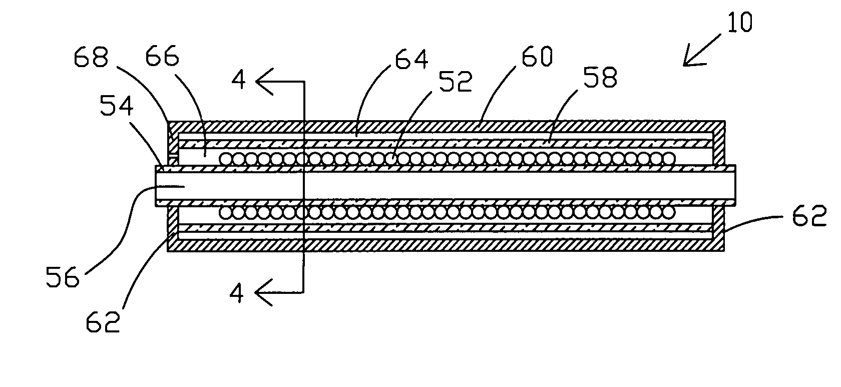
[0035]The presently described hydrophone provides enhanced sensitivity due to the ratios of the mandrel diameters, as discussed hereinafter. Accordingly, this feature provides greater sensitivity than other designs. This is especially useful in hydrophones designed for operation at great depths where sensitivity must be sacrificed to allow static pressure tolerance. This feature allows better performance in the same bottom mounted hydrophone array applications mentioned above.

[0036]Additionally, the present invention utilizes a structure that provides a high pass filter function, which makes the hydrophone insensitive to low frequency signals and static pressure changes. As a result, a change in the operational depth of the hydrophone does not result in a path mismatch of the interferometer. The hydrophone may be manufactured with and maintain a path mismatch of a few millimeters. This small path mismatch minimizes the system laser phase noise, allowing the use of lasers with higher...


PUM


Abstract

An interferometric hydrophone is disclosed that comprises a first mandrel defining an interior that is open to surrounding fluid. A sensing optical fiber is wound upon the first mandrel. A second mandrel is positioned in surrounding relationship with respect to the first mandrel. The first and second mandrels define a first chamber therebetween. A case encloses the first and second mandrels and first chamber. The cylindrical case and the second cylindrical mandrel define a second chamber therebetween, which is sealed and filled with gas or vacuum.

Description

STATEMENT OF GOVERNMENT INTEREST[0001]The invention described herein may be manufactured and used by or for the Government of the United States of America for governmental purposes without the payment of any royalties thereon or therefore.BACKGROUND OF THE INVENTION[0002]1. Field of the Invention[0003]The present invention relates generally to hydrophones and, more particularly, to an enhanced sensitivity fiber optic interferometric hydrophone in which the path mismatch of the interferometer does not vary with changes in static pressure due to depth of operation.[0004]2. Description of the Prior Art[0005]Fiber optic interferometric hydrophones are well known in the art. They generally take one of two forms. In the planar hydrophone form, the hydrophones consist in part of fiber wound spirally into a disc form. In the linear hydrophone form of interest to this invention, the hydrophone consists in part of fiber wound around a cylindrical pressure-compliant sensor mandrel. Though many...

Claims


Application Information

Patent Timeline
IPC IPC(8): G01H9/00
CPCG01H9/004
Inventor AMES, GREGORY H.
Owner UNITED STATES OF AMERICA
Why Eureka
Try Eureka