Recording condition setting method and information recorder using same

a recording condition and information recorder technology, applied in the field of recording condition setting method, can solve the problems of difficult optimization of recording condition directly by using the reproduced signal, the position of the front edge and the rear edge of the record mark cannot be detected with accuracy, and the error correction processing cannot correct an error in the reproduced signal. achieve the effect of obtaining the recording condition of the shortest mark with eas

Inactive Publication Date: 2007-11-13
NEC CORP
View PDF8 Cites 15 Cited by
  • Summary
  • Abstract
  • Description
  • Claims
  • Application Information

AI Technical Summary

Benefits of technology

[0022]In accordance with the first aspect of the present invention, a recording condition under which a suitable signal is reproduced from the test mark is determined for each of the first and second test marks, and then a recording condition under which the shortest mark is suitably formed is determined by using a linear inference interpolation, for example, based on the recording conditions under which the first and second test marks are suitably formed. Accordingly, the recording condition of the shortest mark can be obtained with ease even in the case where the recording condition allowing the shortest mark to be suitably formed cannot be directly determined from the reproduced signal of the shortest mark due to a higher recording density.
[0046]In the recording condition setting method of the first aspect, the information recording device using the same and the program, the recording condition allowing the first and second test marks to be suitably formed is selected based on the reproduced signal of each of the first and second test marks, and the recording condition of the shortest mark is determined based on the selected recording conditions of the first and second test marks. Consequently, since the ratio between the amplitude of the reproduced signal of the longest mark and the amplitude of the reproduced signal of the shortest mark is not larger than about 10%, the recording condition of the shortest mark can be determined with ease even in the case where the recording condition cannot be determined directly by using the reproduced signal of the shortest mark.

Problems solved by technology

In general, if the jitter σ has a value of 15% or above, an error correction processing cannot correct an error in the reproduced signal.
The factors for degrading the jitter σ include an error in setting the recording power, an error in setting the recording strategy, an error in setting the focus, an error in setting the tilt, and so on.
If the amplitude of the reproduced signal is below the slice level 23, there arises a problem in that the positions of the front edge and the rear edge of the record mark cannot be detected with accuracy.
Thus, in the conventional techniques using the jitter or asymmetry value, including the technique described in the patent publication, the optimization of the recording condition directly by using the reproduced signal is difficult to obtain.
This shows that separation of the reproduced signal for the short mark, in particular, is not sufficient to raise an inter-code interference and that the probability of mark generation which is detected in the case of a lower recording density cannot be detected any more using the jitter with high accuracy.
It shows similarly that the detection accuracy of the asymmetry of the shortest mark is reduced in the β technique, and that an accurate judgement is not possible as to whether or not the record mark is suitably formed.
However, the PRML technique requires an additional PRML circuit to complicate the circuit configuration.
In addition, since the bit error rate is calculated in the PRML technique by comparing the known data and the PRML detected recorded / reproduced data, the original data used for this comparison must be given data, and thus are difficult to handle in a general processing scheme unlike the case using the jitter or the asymmetry value.

Method used


Image

  • Recording condition setting method and information recorder using same
  • Recording condition setting method and information recorder using same
  • Recording condition setting method and information recorder using same

Examples


example 1

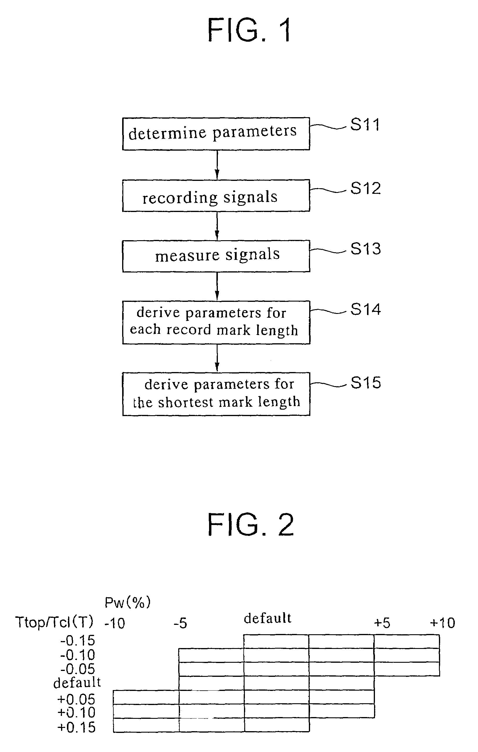
[0074]As an example, an experiment was performed while using an optical disk drive, which mounts thereon an optical head having a numerical aperture NA of 0.85 and a laser wavelength λ of 405 nm. In the experiment, the recording condition for recording on a phase-change optical disk having an overcoat layer of 0.1 mm thickness and running at a linear speed of 5 m / s, with the shortest mark for the (1,7) RLL encoding scheme being set at 0.13 μm (the shortest bit length corresponding to 0.104 μm / bit) was determined based on the procedure shown in FIG. 1. The (n−1)-pulse train shown in FIG. 17B was used as the driving waveform of the laser for forming the record mark on the optical disk. In the optical disk drive, each of the parameters other than the recording power Pw, top width Ttop and rear edge cooling width Tcl was set at the default read from the optical disk itself in step S1 (FIG. 1).

[0075]FIG. 2 exemplifies combinations of changes in the recording condition. In step S12 (FIG. ...

example 2

[0090]As an example, an experiment was performed using an optical disk drive mounting thereon an optical head having a numerical aperture NA of 0.65 and a laser wavelength λ of 405 nm. In the experiment, the recording condition for recording on a phase-change optical disk having an overcoat layer of 0.6 mm thickness, with the 2T shortest mark length (Lmin) for the (1,7) RLL encoding scheme being set at 0.125 μm, was determined based on the procedure shown in FIG. 5. The ratio between the amplitude of the signal reproduced from the longest mark and the amplitude of the signal reproduced from the shortest mark upon setting the 2T shortest mark length at 0.125 μm was not more than 10% and the jitter of the reproduced signal including the signal reproduced from the shortest mark exceeded 15%, whereby it was impossible to determine the parameters etc. of the recording strategy directly by using the reproduced signal.

[0091]In the experiment, the (n−1)-pulse train shown in FIG. 17B was use...


PUM

PropertyMeasurementUnit
thicknessaaaaaaaaaa
thicknessaaaaaaaaaa
thicknessaaaaaaaaaa

Abstract

A test pattern including a first test mark which is one unit-record-length longer than a shortest mark among modulating codes and a second test mark which is two or more unit-record-lengths longer than the shortest mark is recorded under a plurality of recording conditions (step S2). The recorded test pattern is reproduced (step S3), and based on a plurality of reproduced signals thus obtained, recording conditions allowing the first test mark and the second test mark, respectively, to be suitably recorded are selected (step S4). A recording condition for the shortest mark is determined by inference based on the recording conditions of the first test mark and the second test mark.

Description

TECHNICAL FIELD[0001]The present invention relates to a recording condition setting method, an information recording device using the same and a program and, more particularly, to a recording condition setting method for suitably forming a plurality of record marks including a record mark near the optical diffraction limit, an information recording device using the same and a program.BACKGROUND TECHNOLOGY[0002]In recent years, large-capacity optical disks represented by DVD etc. are widely used. Upon recording information on the optical disk, an information-recording optical disk drive is used to focus a recording laser beam onto the information recording surface of the optical disk to form record marks thereon. Upon reproducing the information from the optical disk, information-reproducing optical disk drive is used to focus a reproducing laser beam onto the information recording surface of the optical disk to detect the reflected beam modulated by the record marks to reproduce the...

Claims


Application Information

Patent Timeline
Patent Type & Authority Patents(United States)
IPC IPC(8): G11B15/52G11B7/0045G11B7/125
CPCG11B7/1267G11B7/00456
Inventor NAKANO, MASAKIIWANAGA, TOSHIAKIICHIMURA, TUTOMU
Owner NEC CORP
Why Eureka
Try Eureka