Driving method for electro-optical apparatus, electro-optical apparatus and electronic equipment

a technology of optical apparatus and driving method, which is applied in the direction of non-linear optics, static indicating devices, instruments, etc., can solve the problems the risk of uneven luminance in the vertical direction of the liquid crystal display panel, so as to improve the quality of the motion picture, control the uneven luminance in the vertical direction, and reduce flicker

Active Publication Date: 2007-11-27
138 EAST LCD ADVANCEMENTS LTD
View PDF33 Cites 23 Cited by
  • Summary
  • Abstract
  • Description
  • Claims
  • Application Information

AI Technical Summary

Benefits of technology

[0030]In this arrangement, in a two-terminal type active matrix liquid crystal display device using the two-terminal switching element, such as a non-linear resistant element including an MIM element as the switching element of the each pixel, control of unevenness in luminance in the vertical direction is achieved. In addition, when the non-data signal can be written to obtain a black display of the pixels, the advantage that the quality of the motion picture is improved is achieved at the same time.
[0031]In this electro-optical apparatus, the each frame can be divided into a first sub field and a second sub field, and a data signal having the opposite polarity from the previous frame is written during the first sub field of the each frame, and the non-data signal is written during the second sub field of the each frame. In this arrangement, a data signal of positive polarity or of negative polarity is

Problems solved by technology

In the related art in which frame inversion driving is performed, as in Japanese Unexamined Patent Application Publication No. 8-334741 described above, there is a risk in which unevenness of luminance occurs in the vertical direction on the liquid crystal display panel.
In the related art of Japan

Method used


Image

  • Driving method for electro-optical apparatus, electro-optical apparatus and electronic equipment
  • Driving method for electro-optical apparatus, electro-optical apparatus and electronic equipment
  • Driving method for electro-optical apparatus, electro-optical apparatus and electronic equipment

Examples


first embodiment

[0051]Referring to FIG. 1 to FIG. 7, a liquid crystal display device will be described.

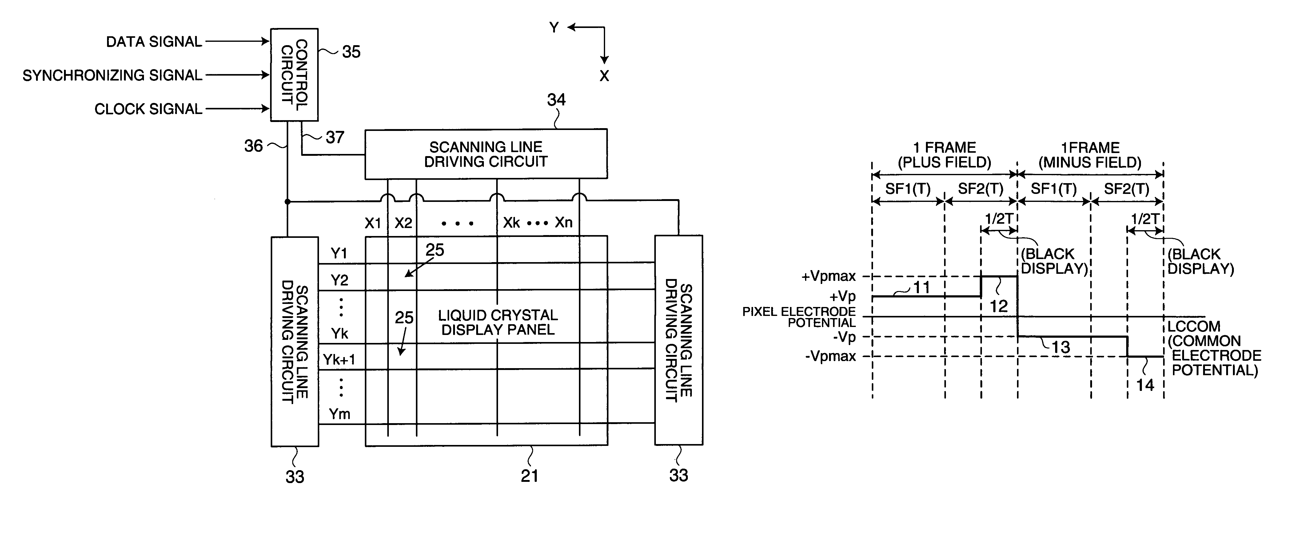
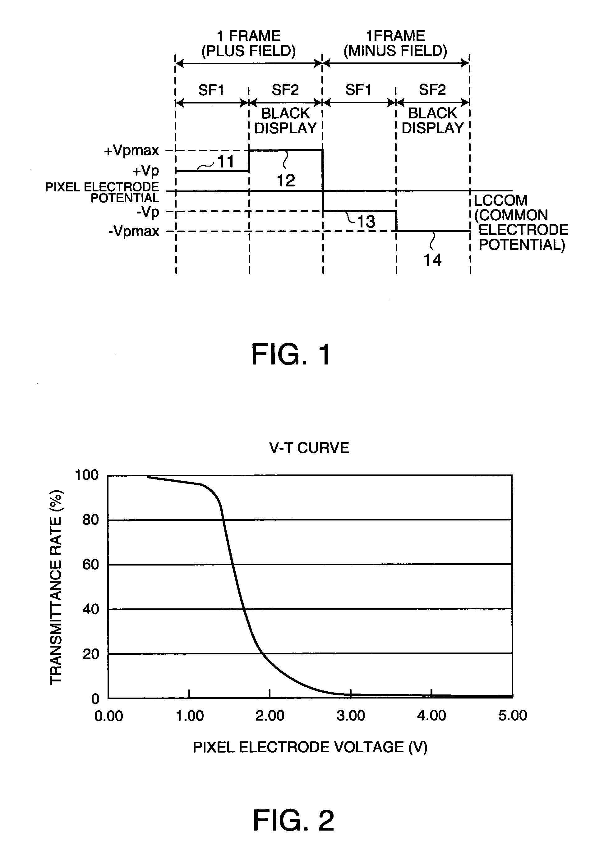
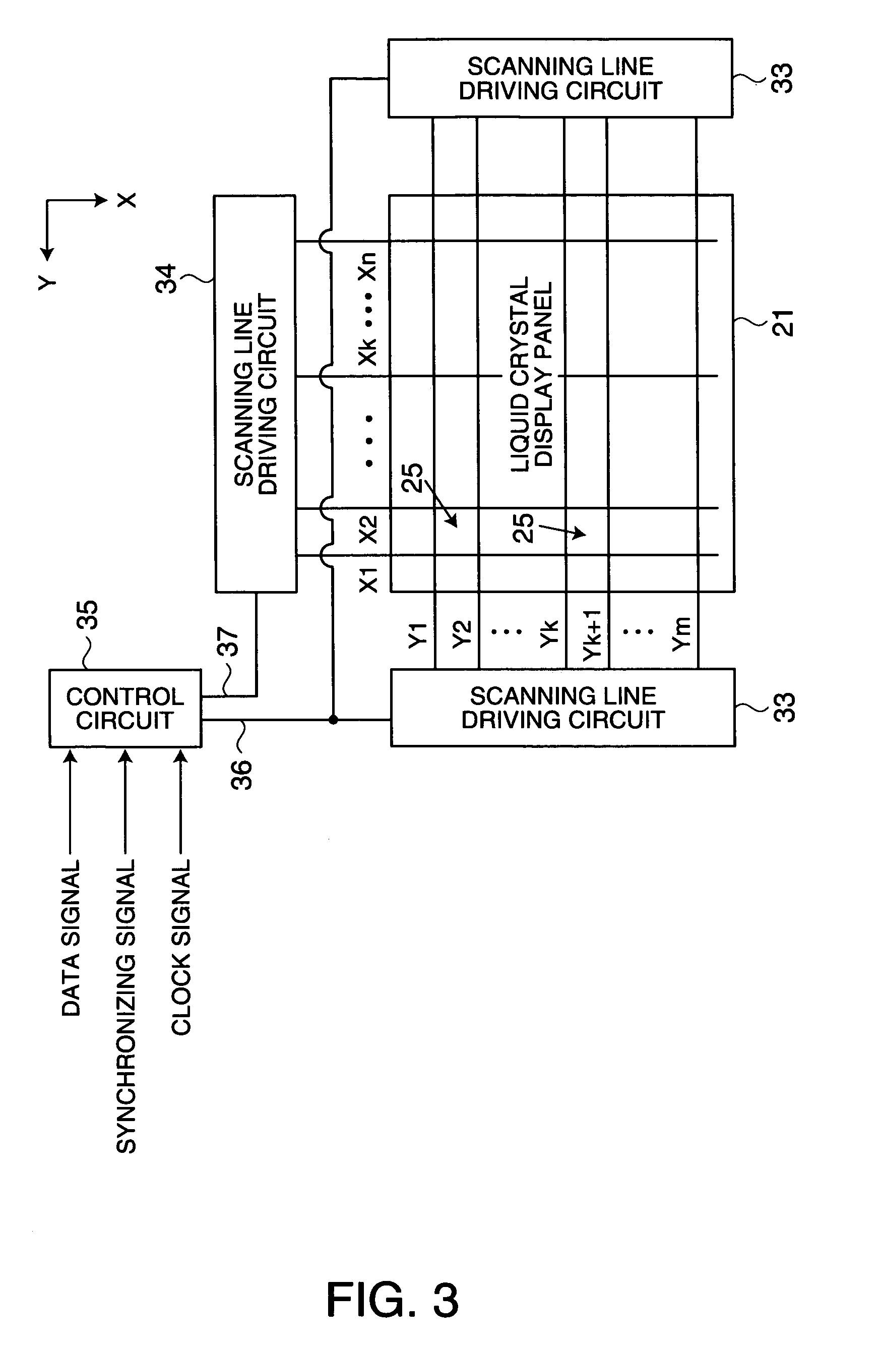
[0052]FIG. 1 shows a driving method for the liquid crystal display device according to the first embodiment, and FIG. 2 shows a V-T characteristic (Voltage-Transmittance ratio characteristic) of the liquid crystal used in the liquid crystal display device. FIG. 3 schematically shows an electrical structure of a driving circuit of the liquid crystal display device, and FIG. 4 shows part of an electrical equivalent circuit of a liquid crystal display panel.

[0053]The liquid crystal display device according to the first embodiment is a three-terminal type active matrix liquid crystal display device employing a three-terminal switching element, such as a thin film transistor (TFT), and its display mode is a normally white mode. This liquid crystal display device performs frame inversion driving for writing a data signal of positive polarity and a data signal of negative polarity to each pixel via swit...

second embodiment

[0083] thus arranged, the following advantage is obtained in addition to the aforementioned advantages (a) to (d).

[0084]A sufficient period of time can be secured for writing and retaining the data signal, and hence brighter display is achieved.

third embodiment

[0085]FIG. 9 shows a driving method for a liquid crystal display device according to the invention. Frame inversion driving for the liquid crystal display device of this embodiment differs only in that one frame for writing the aforementioned non-data signals 12, 14 is provided respectively between two frames to which the aforementioned data signals11, 13 having opposite polarities are written respectively. In other words, the period time for writing each data in the sequence of the aforementioned data signal 11, the non-data signal 12, the data signal 13, and the non-data signal 14 is configured to be one frame having the same time length.

[0086]According to the third embodiment thus arranged, the following advantages are obtained in addition to the aforementioned advantages.

[0087]Control of timings for writing the data signals 11, 13 and the non-data signals 12, 14 is facilitated, and a sufficient period of time can be secured for writing the data signals.

[0088]When the cycle of tw...


PUM


Abstract

The invention provides a driving method for an electro-optical apparatus, the electro-optical apparatus, and electronic equipment in which unevenness of luminance in the vertical direction can be controlled. A data signal is written to pixels in a first sub field SF1 and a non-data signal, having the same polarity as the data signal, and of the maximum voltage is written to the pixels in a second sub field SF2 in each frame. When proceeding from SF1 to SF2, variations in potential applied to each signal line can be decreased, and the amount of leakage of each pixel electrode potential is reduced. After having obtained a black display (in the case of a normally white mode) by writing the non-data signal, a data signal having the opposite polarity from the data signal in the previous frame is written to the pixels. Since a black display is in the stable area of a V-T curve of the liquid crystal, and variations in transmittance ratio can be small even when the voltage is varied to some extent, variations in transmittance rate of the liquid crystal at the each pixel, that is, unevenness of luminance when proceeding from the SF2 to the subsequent frame SF1 is small.

Description

BACKGROUND OF THE INVENTION[0001]1. Technical Field of Invention[0002]The present invention relates to a driving method for an electro-optical apparatus, an electro-optical apparatus, and electronic equipment.[0003]2. Description of Related Art[0004]As an electro-optical apparatus in the related art, an active matrix liquid crystal display device provided with thin film transistors for each of a plurality of pixels disposed in a matrix, wherein an electric potential of a common line opposing a pixel electrode of each pixel via a liquid crystal is inverted on a field-to-field basis, is known. See, for example, FIG. 4 in Japanese Unexamined Patent Application Publication No. 8-334741. In this liquid crystal display device, a video signal of positive polarity and a video signal of negative polarity are written to each pixel alternately on a field-to-field basis and the liquid crystal is driven in an alternating current system by inverting the potential of the common line on a field-to-...

Claims


Application Information

Patent Timeline
IPC IPC(8): G09G3/36G02F1/133G09G3/20
CPCG09G3/3614G09G3/3648G09G2320/0209G09G2310/06G09G2300/088G02F1/133
Inventor HOSAKA, HIROYUKI
Owner 138 EAST LCD ADVANCEMENTS LTD
Why Eureka
Try Eureka