

Light scanning device, scanning line adjusting method, scanning line adjusting control method, image forming apparatus, and image forming method
- Summary
- Abstract
- Description
- Claims
- Application Information
AI Technical Summary
Benefits of technology
Problems solved by technology
Method used
Image

Examples
first embodiment
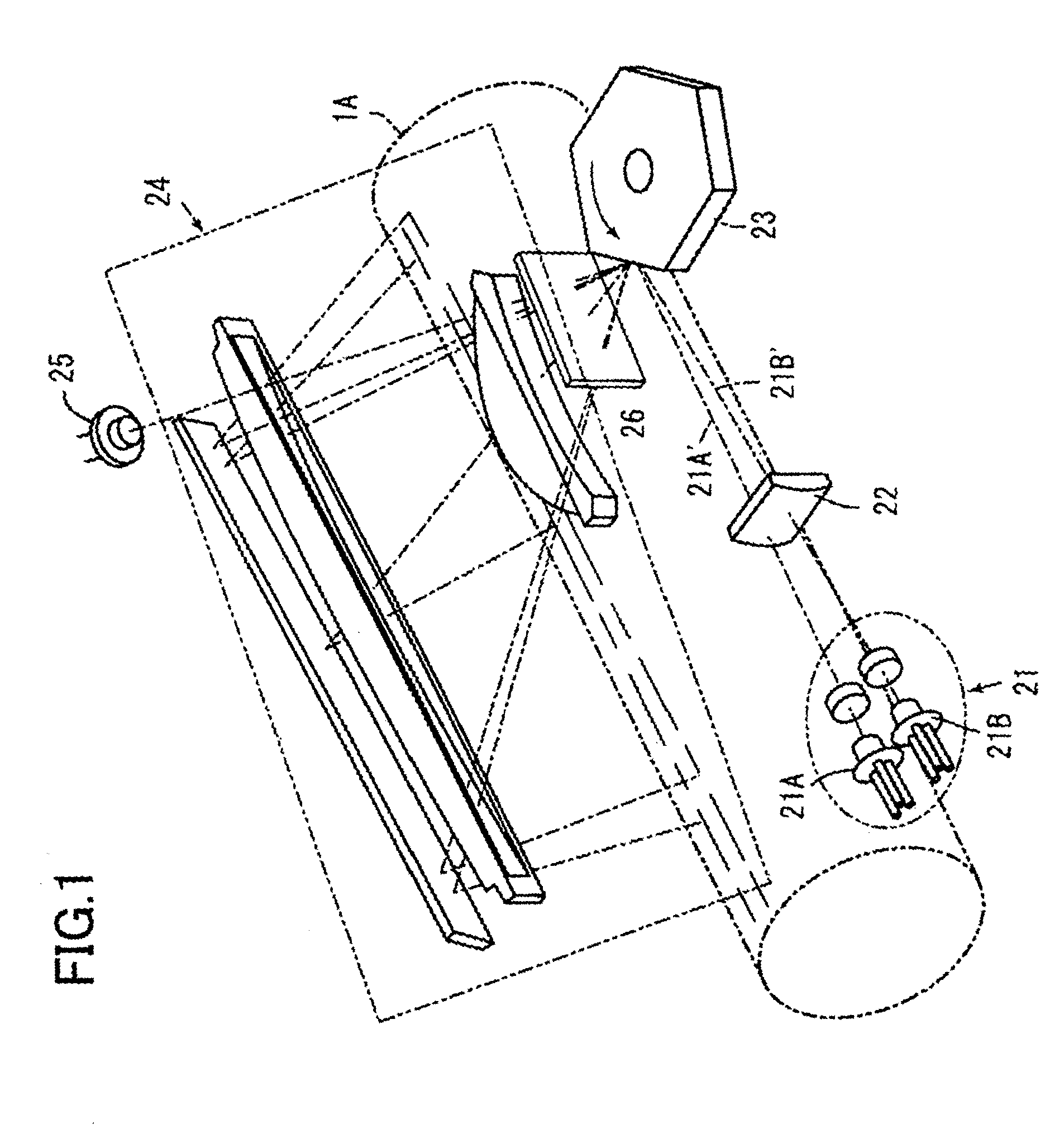
[0108]FIG. 1 shows a basic structure of a light scanning device 20 for the above-described plural photoconductive drums according to the present invention.
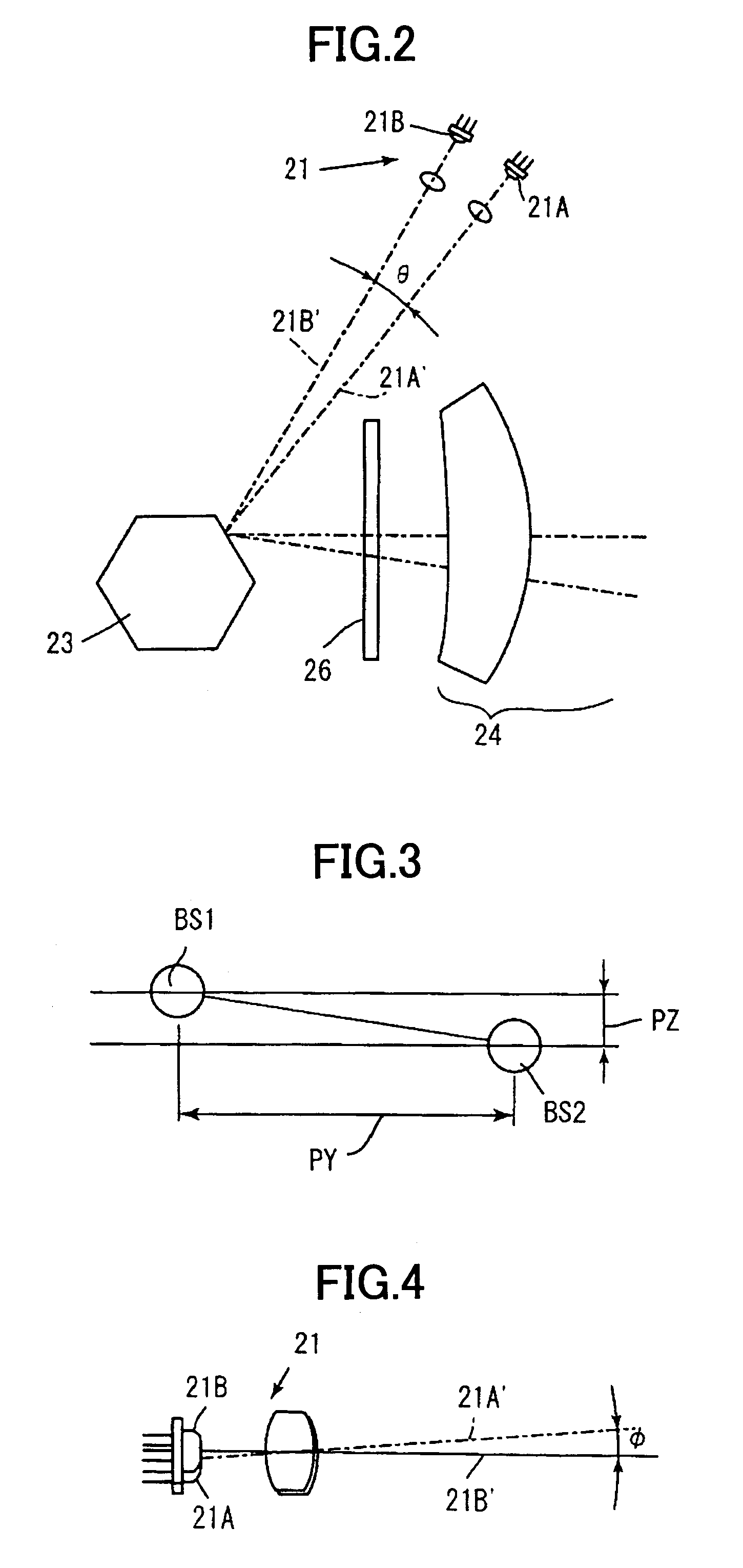
[0109]In FIG. 1, two light beams 21A′ and 21B′ emitted from a light source device 21 including two semiconductor lasers 21A and 21B are focused on a deflection reflection surface of a polygon mirror 23 in terms of a sub scanning direction by a cylindrical lens 22. The polygon mirror 23 functions as a deflector. Then, using the focused light beams 21A′ and 21B′, the polygon mirror has a function of forming long line images in a main scanning direction. A second part 24 of an imaging optical system including an fθ lens scans a scanned surface (the photoconductive drum 1A, for example) by forming light spots thereon. It should be noted that in FIG. 1, the light source device 21 is constituted by the semiconductor lasers and coupling lenses, but the present invention is not limited to this configuration.
[0110]When the light scanning d...
second embodiment
[0153]Next, the present invention will be described.
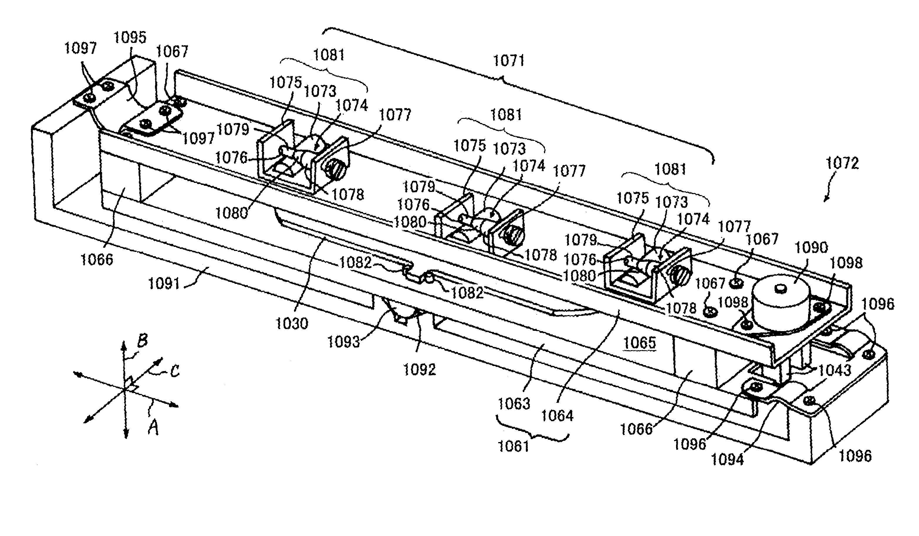
[0154]FIG. 15 shows a light scanning device 1020 that is a tandem type writing optical system. The light scanning device 1020 uses a scanning lens, but may use either of the scanning lens and a scanning mirror. For simplicity, only two stations are shown in FIG. 15. However, four stations may be provided symmetrically with respect to polygon mirrors 1026 and 1027 as deflectors. The image forming apparatus adopts the four stations. The image forming apparatus 1 can form a color image. In a case of forming a color image, the light scanning device 1020 is used for forming the color image.
[0155]The light scanning device 1020 includes two LD units 1021 and 1022 as light sources. The light scanning device 1020 images (focuses) laser beams emitted from the respective LD units 1021 and 1022 on respective photoconductive bodies 1034 and 1038 that are the photoconductive drums as image holding bodies. For this operation, the light scanning d...
PUM
 Abstract
Description
Claims
Application Information