Free point tool with low mass sensor

a free point tool and sensor technology, applied in the field of downhole tools, can solve the problems of easy passing down the well casing of the tool, the string of drilling is often stuck in the well, and the free point tool is complex device that must be operated, and achieves the effects of simple construction, superior sensitivity and linearity, and light weigh

Active Publication Date: 2007-12-04
HUNTING TITAN
View PDF10 Cites 4 Cited by
  • Summary
  • Abstract
  • Description
  • Claims
  • Application Information

AI Technical Summary

Benefits of technology

[0013]Attacking the weight issue first, it was realized that if most of the weight of the entire free point tool assembly could be supported by the wire line, and a sensor design could be devised that was very light, of simple construction, would operate at higher temperatures, and had superior sensitivity and linearity, a substantial improvement would be realized in the utility of the spring type free point tool. The breakthrough occurred when it was realized that a magnetic amplifier principle applied to the sensor itself could provide the linearity and sensitivity, simplicity, ruggedness and light weight that would be needed. The resulting design yielded a low mass sensor assembly that weighs less than five pounds, including the entire sensor structure and the drag springs. The drag springs may be set to approximately ten pounds of tension each, which results in a spring capacity to sensor assembly weight of at least four-to-one. This ratio, which is four times greater than the prior art free point tool described herein above because of the much lower mass of the low mass sensor assembly disclosed herein below, results in much less uncertainty in the drag spring holding power, resulting in reliable measurements that usually only have to be made once. Moreover, the entire tool weight, including the low mass sensor assembly, is approximately 36 pounds, which provides sufficient margin above the tension setting of the drag springs to lower it down hole without sinker bars. Many other advantages will become apparent upon understanding the invention described in the detailed description and accompanying drawings that follow.
[0021]In another aspect of the free point tool of the present disclosure, a slackjoint is integrated into the structure of the free point tool and a coiled, flexible conduit is provided in the slack range for protecting sensor wiring from pressures and corrosive fluids within the well casing.
[0023]In yet another aspect of the free point tool of the present disclosure, the operation of the CCL is interlocked with the sensor assembly to prevent loading of a collar locating signal, without the use of semiconductor diodes.

Problems solved by technology

During well drilling operations in the oil and gas well drilling industry, the drill string often becomes stuck in the well.
Free point tools are complex devices that must operate in extremely harsh environments where they are subject to wide temperature variations, high pressures, corrosive substances, and the like.
Yet, in such conditions, the tool must provide sensitive, reliable measurements of the displacement of the free portion of a well pipe when a tension or torque is applied to the pipe string to cause the displacement.
However, there are a number of well-known problems with its use.
But this requires extra weight in the form of sinker bars to be added to the weight of the tool assembly, plus the other half of the slack joint, to cause the tool to pass down the well casing easily.
If the tension is too little, the drag springs will not support the tool and the measurement will not be repeatable.
Associated with the critical spring tension adjustment is the high degree of uncertainty that the drag springs will have the correct holding power and that an accurate measurement is made at each desired point in the well casing.
Frequently, this uncertainty and the occasional slippage of the springs along the well casing requires that the tool be hauled up, the drag springs reset, and the measurement attempted again.
This characteristic limits the usable sensitivity within a relatively narrow range.
The complexity of this sensor design adds weight, reduces reliability and adds to the maintenance expense.
The added weight exacerbates the drag spring problems described herein above.
Typically, this circuit is provided by semiconductor diodes, which limit the effectiveness of the circuit to about 350 degrees Fahrenheit (350 F.) because the diodes lose their blocking characteristics above that temperature.
Moreover, the shunting effect of the diodes also affects the free point sensor signal if the same wire is used for both functions.
Unfortunately, down-hole temperatures become higher as the depth of the well increases, a circumstance that is more prevalent currently as well drilling extends to deeper levels to access more remote deposits of oil or gas.
It will be appreciated that the weight of the prior art free point tool that must be supported by the drag springs is a major source of the problems with its use.
Further, the prior art sensor design has relatively poor sensitivity, a narrow range of linearity, requires substantial maintenance, requires force to overcome the built-in friction, and requires a relatively complex procedure to reset it for a measurement.
Moreover, the prior art tool is ineffective at temperatures above 350 F.

Method used


Image

  • Free point tool with low mass sensor
  • Free point tool with low mass sensor
  • Free point tool with low mass sensor

Examples


Embodiment Construction

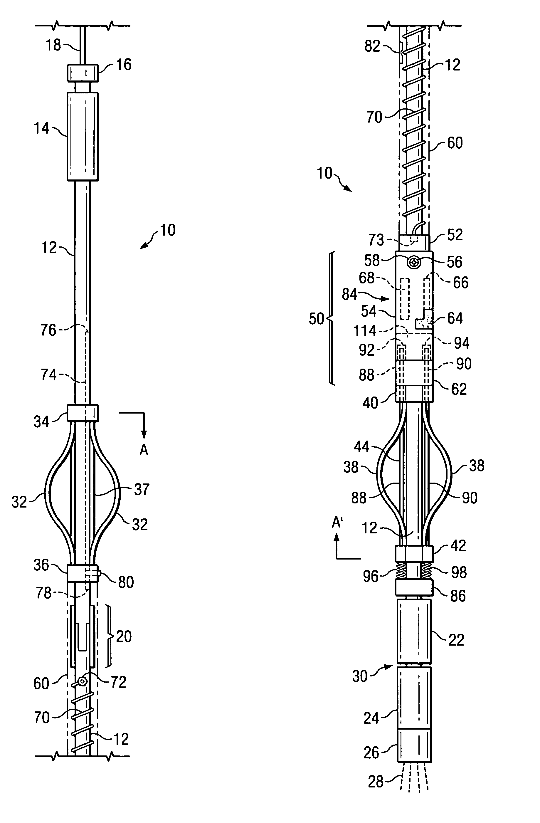
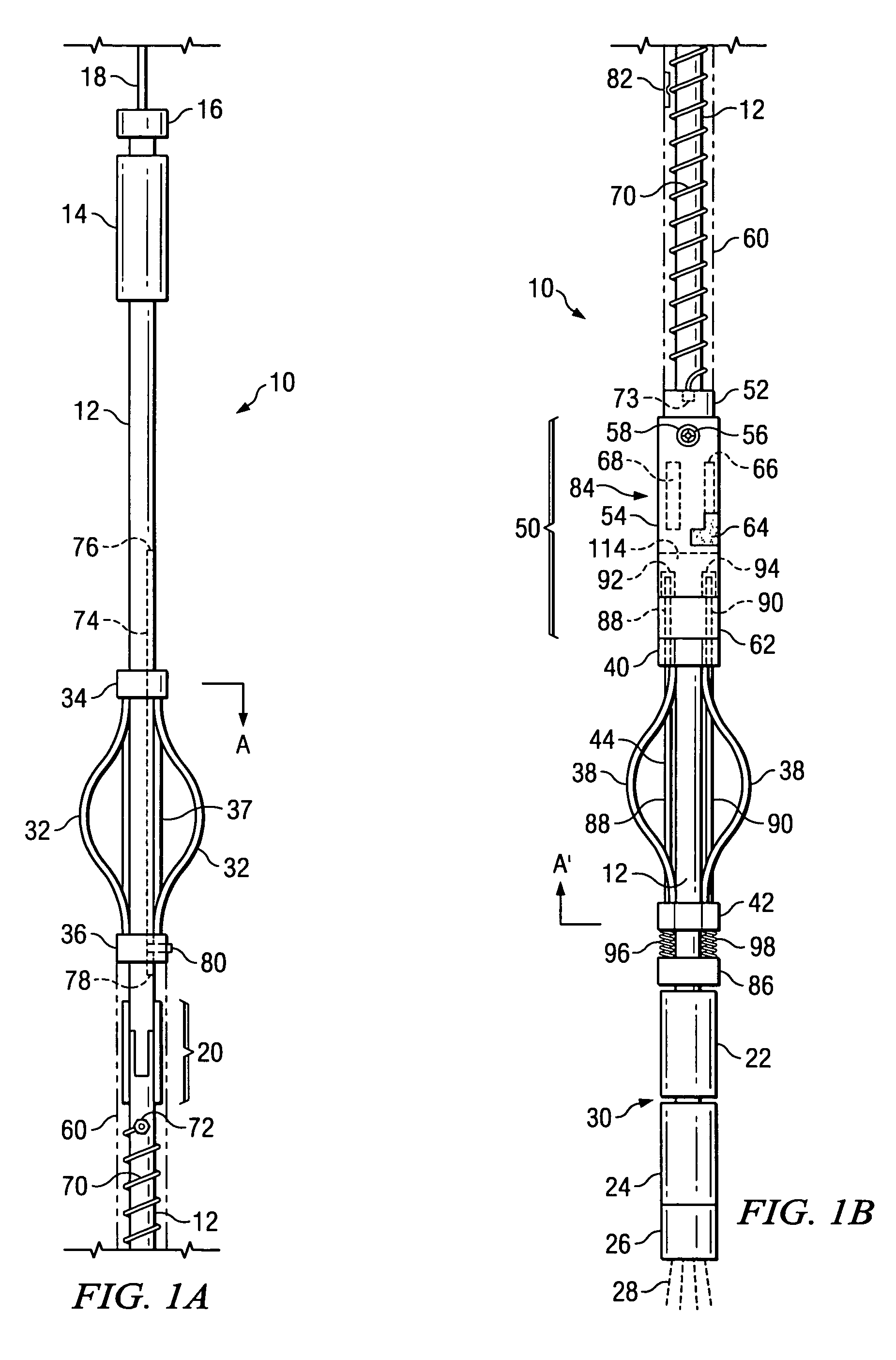
[0052]Referring to FIG. 1A, there is illustrated a first, upper portion of one embodiment of a free point tool according to the present invention. FIG. 1B illustrates a second, lower portion of the embodiment of FIG. 1A. The description of the structures shown in FIGS. 1A and 1B, described together as a single FIGURE, will also serve as an overview of the illustrated embodiment. Further details of both the structure and operation will become clear as the description proceeds to the remaining figures. It will further be appreciated that the orientation of a free point tool, as typical of down hole tools employed in well drilling operations, is to be suspended by a wire line in the well casing, usually below the surface of the earth. In the description which follows, the term “surface” will be taken to mean the surface of the earth and, occasionally, the apparatus and other equipment or personnel associated with the operation of the free point tool.

[0053]The free point tool 10 illustr...


PUM


Abstract

A free point tool comprises an elongated main shaft assembly and a low mass sensor assembly coaxially and slidingly disposed over the elongated main shaft. The low mass sensor assembly is adapted to be supported within the down hole casing by first and second drag spring centralizers coupled respectively to upper and lower ends of the low mass sensor assembly. The low mass sensor assembly comprises a magnetic amplifier sensor disposed in a sensor body and having a variable inductance proportionally responsive to longitudinal and rotational displacement of an adjacent sensor plate portion of a movable sensor sleeve concentric with and enclosing the sensor body, wherein the sensor sleeve is attached to the first drag spring centralizer and the sensor body is attached to the second drag spring centralizer.

Description

BACKGROUND OF THE INVENTION[0001]1. Field of the Invention[0002]The present invention generally relates to down-hole tools for use in oil and gas well holes and, more particularly, down-hole tools used to locate the position of a stuck point of a drill pipe string in the well hole.[0003]2. Background and Description of the Prior Art[0004]During well drilling operations in the oil and gas well drilling industry, the drill string often becomes stuck in the well. Free point tools have long been used to locate the stuck point of the drill string in the well, so that the drill pipe above the stuck point that is not stuck—i.e., “free”—can be removed to permit further operations to loosen the stuck pipe.[0005]Generally, a free point tool includes a lower portion and an upper portion. When installed within a well casing in a well, the upper and lower portions of a free point tool are configured to detect relative movement of one portion of the tool with respect to the other portion. Traditi...

Claims


Application Information

Patent Timeline
Patent Type & Authority Patents(United States)
IPC IPC(8): E21B47/00
CPCE21B47/09
Inventor ESTES, JAMES D.
Owner HUNTING TITAN
Why Eureka
Try Eureka