Blade-thru-slot combustion engine, compressor, pump and motor

a piston-throwing, combustion engine technology, applied in the direction of rotary or oscillating piston engines, rotary piston engines, engine lubrication, etc., can solve the problems of severe inherent limitations of design, increase friction and wear, and reduce performance, so as to reduce the cooling requirements, reduce the internal friction, and reduce the effect of high internal friction

Inactive Publication Date: 2007-12-11
ZAK JUAN
View PDF49 Cites 12 Cited by
  • Summary
  • Abstract
  • Description
  • Claims
  • Application Information

AI Technical Summary

Benefits of technology

[0016]The principal object of the present invention is a rotary internal combustion engine that overcomes the reduced performance, high internal friction, excessive wear and low energy efficiency of conventional reciprocating engines. It is a further object of this invention to overcome shortcomings of prior art toroidal engines which generally include sealing problems, insufficient compression, mechanical complexity and excessive pumping power requirements. It is a further object of this invention to provide a mechanically simple engine that can also be constructed with ceramic materials and thus reduced cooling requirements.
[0017]The BTS engine can work either as an Otto or Diesel engine (only the first is explained below). The engine consists of a static housing, a rotor(s) with a radial blade(s) on its perimeter, a chamber(s) swept by the blade(s), and a planar valve(s) with slot intersecting the chamber(s). Blades and slot valves move synchronously in a way that blades traverse the valves through the slot. Blades and slots have matching shapes that allow such traversal with negligible loss of working fluid through the slots.
[0021]It is a further object of this invention to provide a compressor / pump with lower friction and wear, and lower power demand than conventional reciprocating compressors and pumps. It is also object of the invention to provide a rotary compressor / pump superior to prior art machines in terms of mechanical simplicity, low internal friction, and no internal lubrication requirements. The BTS compressor / pump is very similar to the compressor side of the double-rotor BTS engine, described above.
[0022]It is a further object of this invention to provide a compressed-fluid motor superior to conventional and prior art machines in terms of mechanical simplicity, low internal friction and no internal lubrication requirements. The BTS motor is very similar to the already described expansion side of the BTS double-rotor engine.

Problems solved by technology

This design has severe inherent limitations: pressure and torque arm out of phase, high “inertial” forces between components due to acceleration / deceleration of pistons and change of trajectory of connecting rods, and expansion ratio tied to the compression ratio.
Such limitations reduce performance, increase friction and wear, and reduce energy efficiency.
Technically speaking, the Wankel engine has not completely solved old problems like friction and wear, and has problems of its own, especially low torque and troublesome sealing.
A key problem in prior art toroidal engines is the loss of compressed fluid during the opening and closing of the walls / valves.
Such loss has an important toll on power output and energy efficiency, as it reduces the fuel-burning capacity of the engine, and at the same time increases the pumping power requirements for the compression and exhaust strokes.
Although the Archer and Pekau engines have lower compression losses than previous toroidal designs, reduced fuel-burning capacity and excessive pumping power requirements are still present.
Design limitations do no allow for positive removal of exhaust gases; instead, these remain in the toroidal chamber, between the revolving pistons, and are carried along until they get mixed with the intake charge.
Consequences of these limitations are reduced intake of fresh air, excessive amount of exhaust gases in the intake charge, increased pumping losses, and ultimately lower power output.

Method used


Image

  • Blade-thru-slot combustion engine, compressor, pump and motor
  • Blade-thru-slot combustion engine, compressor, pump and motor
  • Blade-thru-slot combustion engine, compressor, pump and motor

Examples


Embodiment Construction

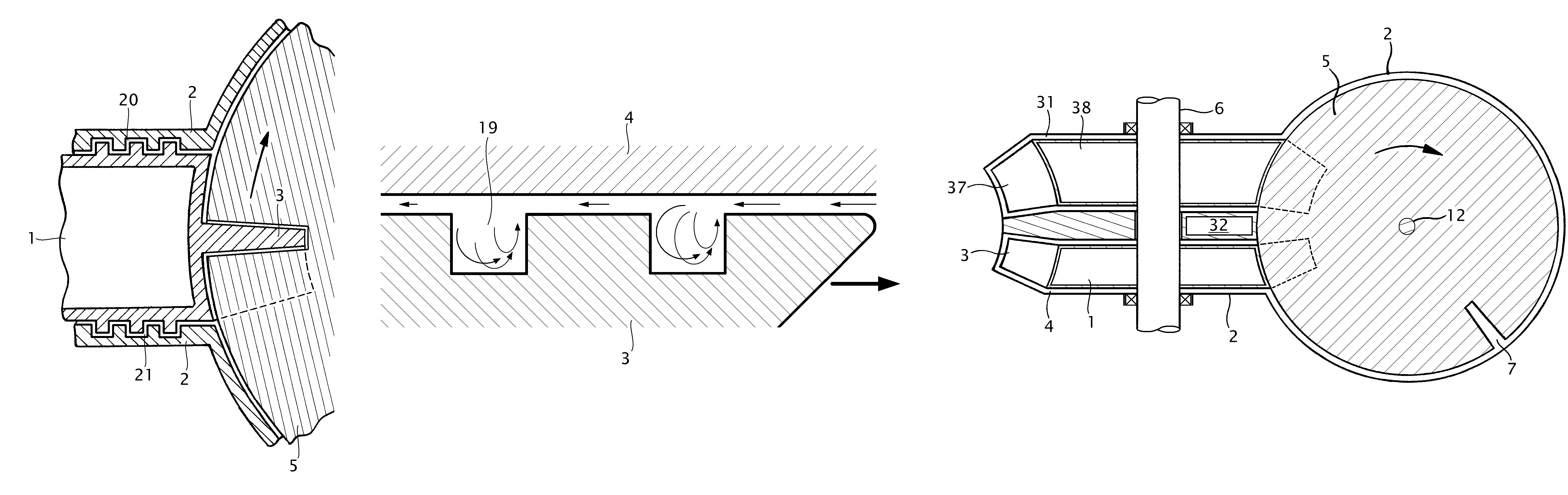
[0053]The blade-thru-slot (BTS) rotary machine can be implemented as a compressor, pump, motor or combustion engine. The following description will sequentially describe each of these implementations.

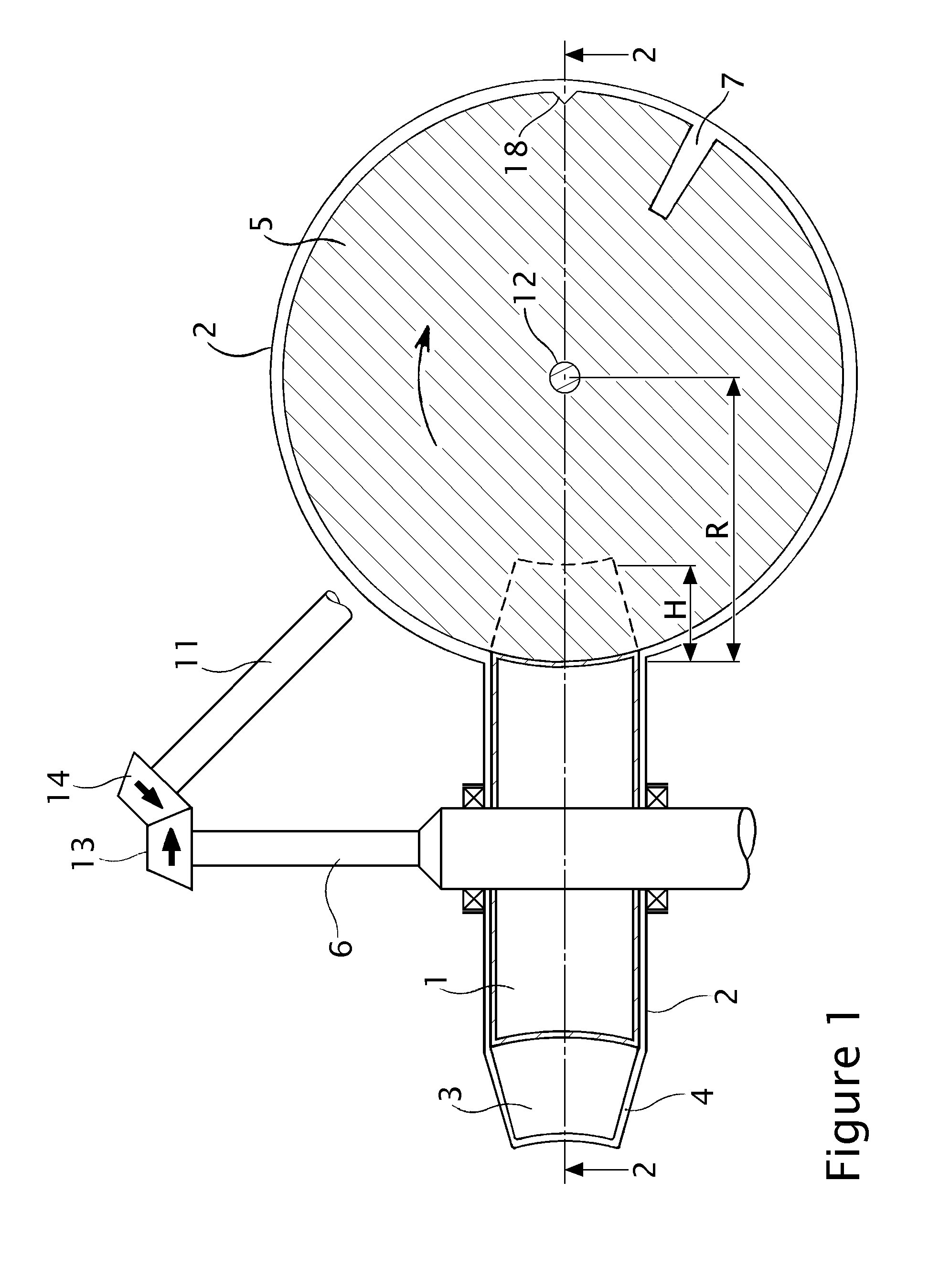
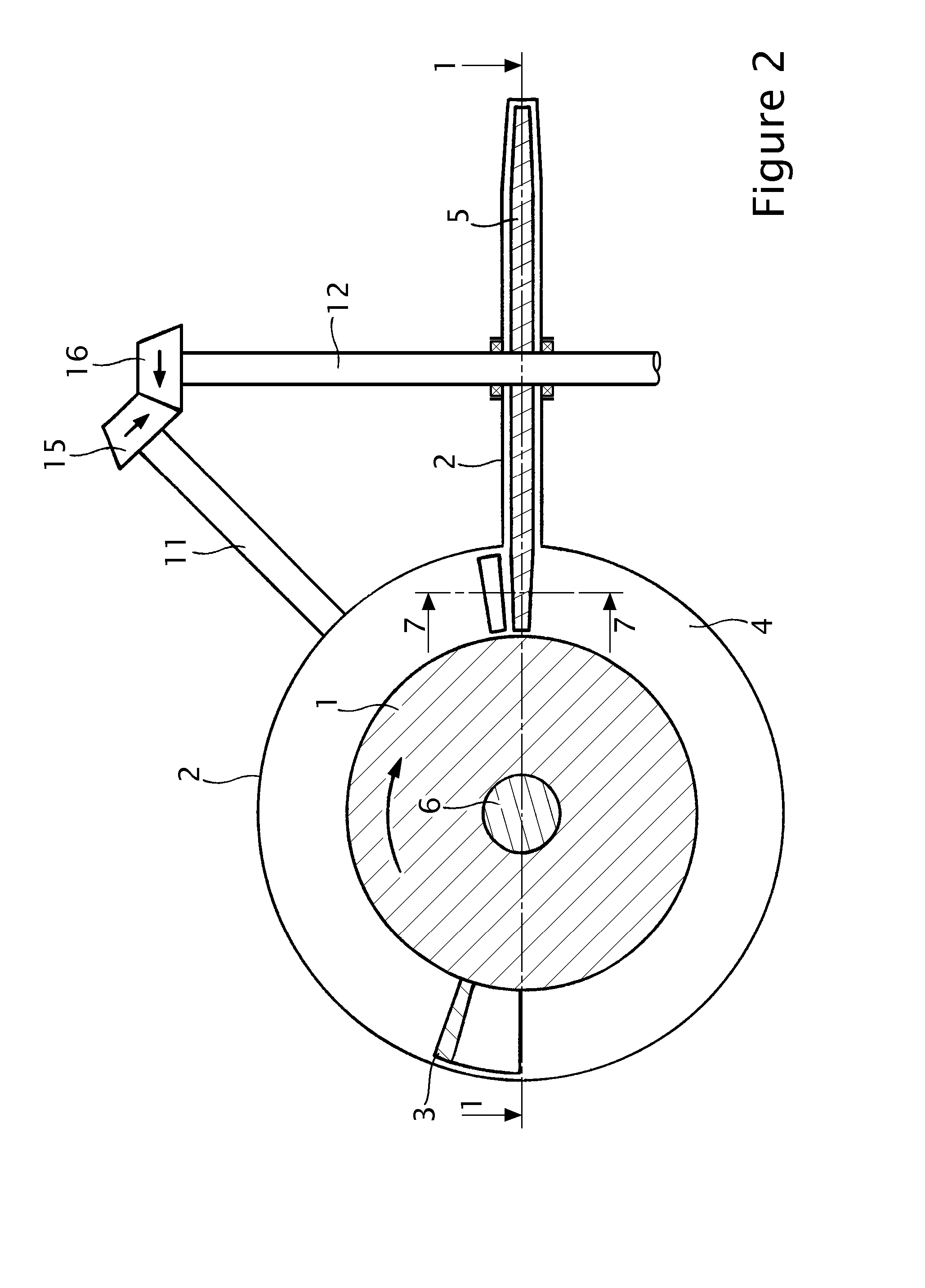
[0054]FIGS. 1 and 2 present schematic views of a BTS compressor or pump. The basic elements are a rotor 1, contained in a static housing 2, with one or more radial blades 3 arranged equiangularly; a chamber 4 swept by the blade(s); and one or more planar slot valves 5, one per blade, also placed radially and equiangularly in the chamber. Rotor 1 (FIG. 3) is mounted and secured on main shaft 6, which receives the driving torque at one of its ends. Blades and slot valves move synchronously to each other in a way that blades 3 timely reach and traverse slots 7. Blades and slots have special matching shapes that allow such traversal with negligible loss of working fluid through the slots; this is further explained below.

[0055]Referring to FIG. 4, the best match between blade 3 (not show) an...


PUM


Abstract

This is simple and efficient rotary machine that can be implemented as compressor, pump, motor and mainly as internal combustion engine. The engine comprises a housing, a rotor(s) with a radial blade(s), a chamber(s) swept by the blade(s), an intersecting planar valve(s) with slot, and a combustion chamber. Blades and slots have matching shapes that allow the traversal of the blades through the slots with negligible loss of air / gases. After traversing the slot, the blade aspires air into one side of the chamber while compresses air on the other side. Fuel is injected in the compressed stream in its way to the combustion chamber, where it is ignited. In a double-rotor implementation, combustion gases are then introduced in the second rotor chamber, just after its blade has traversed the corresponding slot. One side of this blade is pushed by the expansion while the other expels gases from the previous stroke.

Description

BACKGROUND OF THE INVENTION[0001]1. Field of the Invention[0002]This invention relates to a rotary machine that can be implemented as a compressor, pump, motor or combustion engine. This machine is mainly intended for use as an internal combustion engine.[0003]2. Description of the Prior Art[0004]Most internal combustion engines nowadays use reciprocating pistons. This design has severe inherent limitations: pressure and torque arm out of phase, high “inertial” forces between components due to acceleration / deceleration of pistons and change of trajectory of connecting rods, and expansion ratio tied to the compression ratio. Such limitations reduce performance, increase friction and wear, and reduce energy efficiency.[0005]Many rotary designs have been proposed to overcome the inherent limitations of reciprocating engines. Although relegated to niche markets, the Wankel engine has probably been the most successful in commercial terms. Technically speaking, the Wankel engine has not c...

Claims


Application Information

Patent Timeline
Patent Type & Authority Patents(United States)
IPC IPC(8): F02B53/04E21B33/06F01C21/08F01C3/02F01C3/06F02B53/02F16J15/16F16J15/447
CPCF01C3/02
Inventor ZAK, JUAN
Owner ZAK JUAN
Why Eureka
Try Eureka