Gain monitoring method for optical amplifier and apparatus thereof

a technology of optical amplifier and gain monitoring method, which is applied in the direction of transmission monitoring, optical transmission, electromagnetic transmission, etc., can solve the problem of hardly being able to accurately detect the generation amount of noise light generated inside the optical amplifier, the calculation of error in the generation amount of noise light, and the possibility of error, so as to achieve high accuracy operation control and accurate detection of signal light gain

Inactive Publication Date: 2007-12-11
FUJITSU LTD
View PDF20 Cites 5 Cited by
  • Summary
  • Abstract
  • Description
  • Claims
  • Application Information

AI Technical Summary

Benefits of technology

[0012]In the gain monitoring method for the optical amplifier and the apparatus thereof as described above, a part of the signal light input to the optical amplifier is branched as the input monitor light to be modulated, and also a part of the signal light output from the optical amplifier is branched as the output monitor light, and then, the modulated input monitor light and the output monitor light are multiplexed with each other. As a result, the multiplexed light contains the interference component (beat component), which is changed in proportion to the gain of the optical amplifier regardless of a noise light generated in the optical amplifier, due to the interference by the input monitor light and the output monitor light. Therefore, by extracting the interference component from the electrical signal obtained by photo-electrically converting the multiplexed light, it becomes possible to detect the gain for the signal light in the optical amplifier.
[0013]As a result, according to the gain monitoring method for the optical amplifier and the apparatus thereof in the present invention, it is possible to accurately detect the gain for the signal light regardless of the noise light generated inside the optical amplifier. If an operation of the optical amplifier is controlled utilizing the method and apparatus, it becomes possible to realize a high accurate operation control.

Problems solved by technology

However, in the conventional technique described above, there is a problem in that the generation amount of the noise light generated inside the optical amplifier is hardly to be accurately detected.
Therefore, there is a possibility of an error in the calculated generation amount of the noise light.
Further, in the case where the power of the noise light is monitored utilizing the optical filter for noise light elimination, since the noise light power in a band deviated from a signal light wavelength is monitored, there is a possibility of an error due to a difference of wavelength.
In a system where the optical amplifiers are connected in multi-stages for example, such an error in the generation amount of the noise light in each stage is gradually accumulated even if the error in each stage is slight.
Therefore, there is caused a problem of the accuracy reduction in the AGC, ALC or the like.

Method used


Image

  • Gain monitoring method for optical amplifier and apparatus thereof
  • Gain monitoring method for optical amplifier and apparatus thereof
  • Gain monitoring method for optical amplifier and apparatus thereof

Examples


Embodiment Construction

[0023]There will be described embodiments for implementing the present invention, with reference to the accompanying drawings. The same reference numerals denote the same or equivalent parts in all drawings.

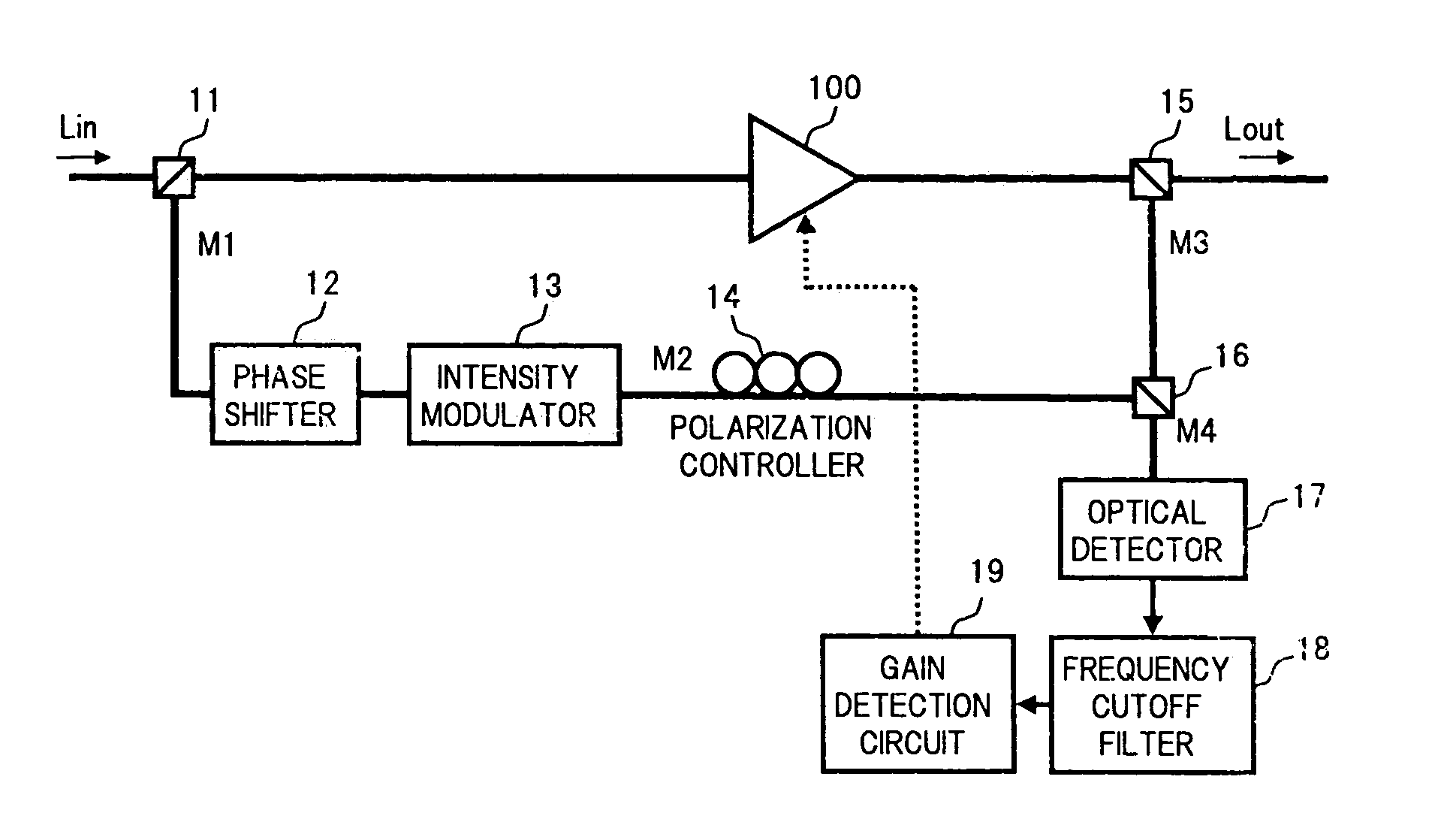
[0024]FIG. 1 is a block diagram showing one embodiment of an apparatus applied with a gain monitoring method for an optical amplifier according to the present invention.

[0025]In FIG. 1, the present apparatus comprises: an optical branching device 11 as a first branching section that branches a part of a signal light Lin input to an optical amplifier 100, as an input monitor light; a phase shifter 12 as a phase adjusting section that adjusts a phase of the input monitor light; an intensity modulator 13 as a modulating section that modulates the input monitor light output from the phase shifter 12; a polarization controller 14 as a polarization state adjusting section that controls a polarization state of the modulated input monitor light; an optical branching device 15 as a second...


PUM


Abstract

An object of the invention is to realize a gain monitoring method for an optical amplifier and an apparatus thereof, capable of detecting a gain for a signal light regardless of a noise light generated inside the optical amplifier. To this end, in the gain monitoring method according to the present invention, a part of a signal light input to an optical amplifier is branched as an input monitor light, and the input monitor light is modulated, and also a part of a light output from the optical amplifier is branched as an output monitor light, so that the modulated input monitor light and the output monitor light are multiplexed. Then, the multiplexed light is converted into an electrical signal, an interference component contained in the electrical signal is extracted, and a gain for the signal light in the optical amplifier is detected based on the interference component.

Description

BACKGROUND OF THE INVENTION[0001]1. Field of the Invention[0002]The present invention relates to a gain monitoring method and an apparatus thereof, for monitoring accurately a signal gain in an optical amplifier used for optical communications.[0003]2. Description of the Related Art[0004]In optical fiber communications, the introduction of a wavelength division multiplexing (WDM) system has been made as a system for increasing the transmission capacity. In the WDM system, an optical amplifier for compensating for a transmission loss in an optical fiber is used, to enable the long-distance transmission. As the optical amplifier used for the WDM system, for example, there is used a rare-earth element doped optical fiber amplifier, a Raman amplifier, or a semiconductor optical amplifier. As an optical amplifier mostly introduced into a practical system, there is an erbium doped optical fiber amplifier (EDFA). The EDFA has become in practical use as the optical amplifier capable of ampl...

Claims


Application Information

Patent Timeline
Patent Type & Authority Patents(United States)
IPC IPC(8): H04B10/00H01S3/13H01S3/06H01S3/067H01S3/10H01S3/131
CPCH04B10/0777H04B10/2931H04B10/0797H04B2210/077
Inventor WATANABE, MANABU
Owner FUJITSU LTD
Why Eureka
Try Eureka