Failure resistant flame retardant vapor barrier insulation facing

a technology of vapor barrier and flame retardant, which is applied in the field can solve the problems of wmp-10® facing torn or damaged, material that is not recyclable, and subject to failure due to physical attributes, and achieves enhanced puncture resistance and tear resistance of flame retardant facing material

Active Publication Date: 2007-12-18
IRIS WOVEN U S LLC
View PDF32 Cites 21 Cited by
  • Summary
  • Abstract
  • Description
  • Claims
  • Application Information

AI Technical Summary

Benefits of technology

[0016]It is another objective of the present invention to provide enhanced puncture resistance to the flame retardant facing material.
[0017]It is a further objective of the present invention to provide enhanced tear resistance to the flame retardant facing material.
[0021]The gray pigmented masterbatch is used for increased opacity, which may be modified for opacity and color preferences. For example, if a white appearance is desired, the inner coating layer can include white pigment instead of gray pigment. By using two coating layers, opacity is increased from the additional thickness of the second coating layer as well as the layer-to-layer optical interface.

Problems solved by technology

Such facing materials are not “recyclable” due to the difficulty in separating the components of the laminates.
While WMP-10® meets flame spread tests, it is subject to failure due to physical attributes.
It is not uncommon for WMP-10® facing to become torn or damaged by personnel unloading insulation at a construction site.
Once the facing is torn or punctured, the vapor barrier is no longer effective.
Further, currently available facing products are somewhat difficult to install because the layer that lends body to the facing, typically scrim, lacks strength and recyclability due to the mixture of polymer and paper.
When used in metal building insulation, the insulation facing is inadequate to support the weight of installing personnel.
However, prior attempts at using coated polyolefin woven substrates have been unsuccessful in producing insulation facing that satisfies flame spread and smoke generation tests when the facing is laminated to the insulation.
In contrast, a product with a polymeric layer on two sides typically fails the flame spread and smoke generation tests, particularly the flame spread test.

Method used


Image

  • Failure resistant flame retardant vapor barrier insulation facing
  • Failure resistant flame retardant vapor barrier insulation facing
  • Failure resistant flame retardant vapor barrier insulation facing

Examples


examples

[0057]The following examples are illustrative of the present invention and demonstrate the improved properties of the invention. It is known by those skilled in the art how variations and modifications of the examples can be made without departing from the scope of the invention as disclosed. Cited coating layer proportions, woven substrate tape material, denier ranges and tape counts have been empirically determined. Variations from composite proportions of the coextruded layers, pigment used, woven substrate tapes per inch range, and denier range and types of polyolefin used would be within the scope of the present invention.

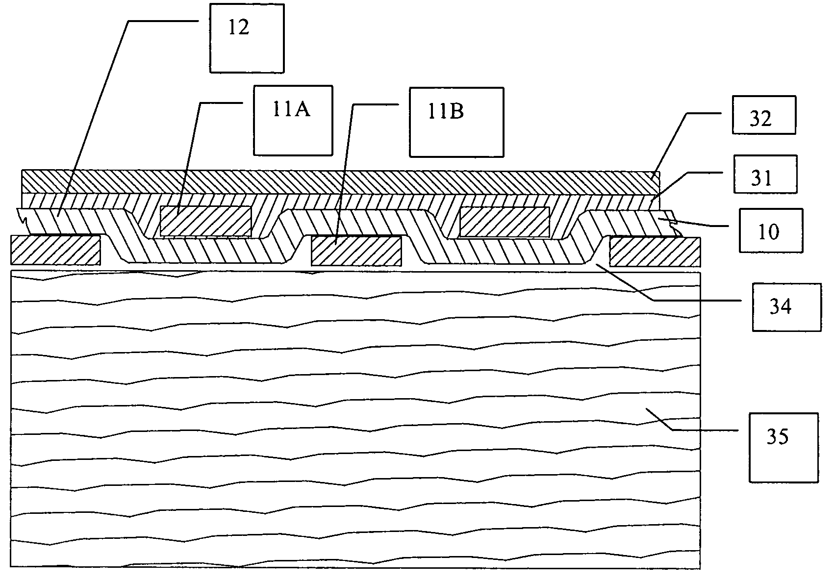
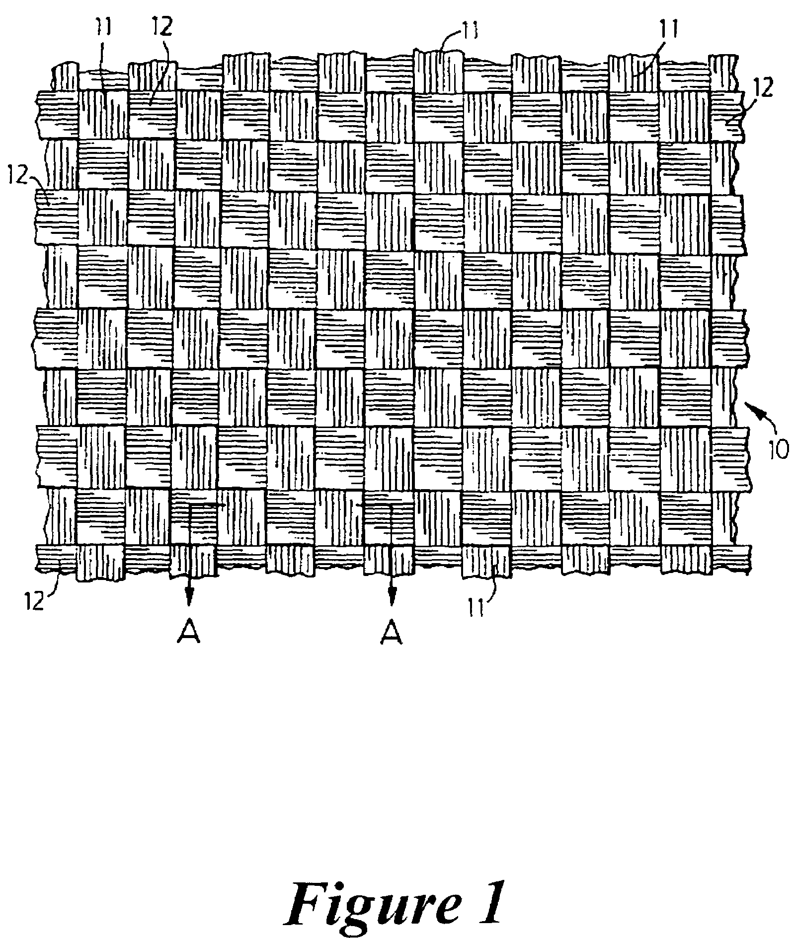
[0058]A woven substrate is woven from FR polyolefin tapes, for example high density polyethylene. The resulting substrate has 8 tapes / inch in the warp direction of 900 denier high density polyethylene and 3 tapes / inch in the weft direction of 1200 denier high density polyethylene.

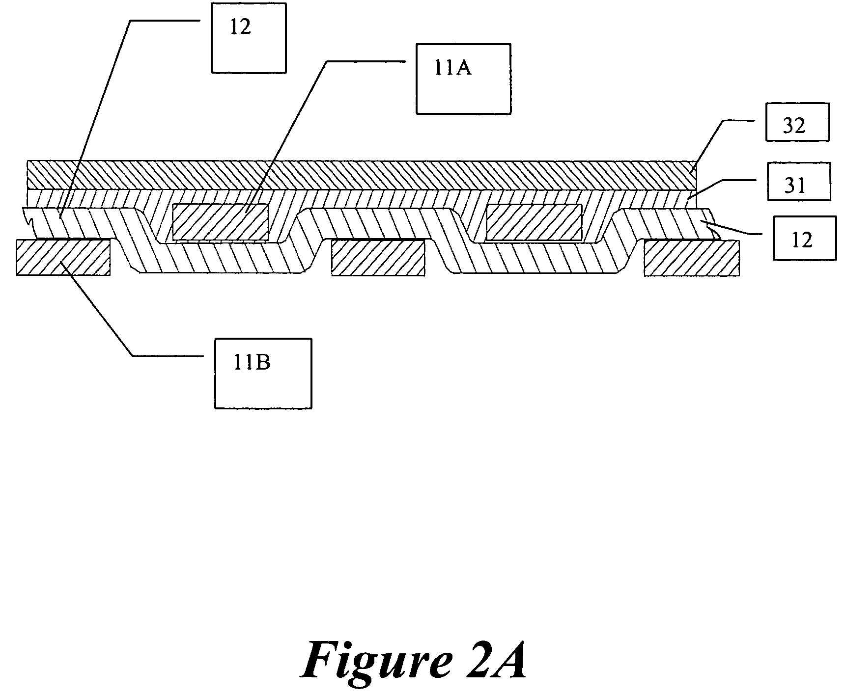
[0059]A two layer coating is then added to this woven substrate. Both layers are ...


PUM

PropertyMeasurementUnit
total thicknessaaaaaaaaaa
thickaaaaaaaaaa

Abstract

A failure resistant, flame retardant vapor barrier facing for insulation is disclosed. The facing is comprised of a coating and a backing. The coating comprises a pair of coextruded composites each composite comprised of FR material, UV blocking material, pigment material and a polyolefin (e.g., LDPE). The backing is a woven substrate woven from flame retardant polyolefin (e.g., HDPE) tapes. The woven substrate is laminated to building insulation using an adhesive. The woven substrate lends strength, flexibility and form to the facing.

Description

CROSS REFERENCE TO RELATED APPLICATIONS[0001]This application is a divisional of application Ser. No. 10 / 342,788, filed Jan. 15, 2003, now abandoned, which claims priority from pending U.S. provisional patent application Ser. No. 60 / 348,760, filed Jan. 15, 2002.FIELD OF THE INVENTION[0002]The present invention relates to flame retardant facing for building insulation. In particular, this invention relates to recyclable flame retardant facing comprising a woven substrate and one or more coating layers that satisfies flame spread and spoke generation specifications of building code administrators.BACKGROUND OF THE INVENTION[0003]Insulation for buildings is faced with a flame retardant material that serves a dual purpose of acting as a vapor barrier and as a flame retardant material. The facing is adhered to the insulation, for example fiberglass insulation batts of varying thickness. Typically the facing is laminated to a single side of the insulation batt, although in particular appl...

Claims


Application Information

Patent Timeline
Patent Type & Authority Patents(United States)
IPC IPC(8): B32B17/04B32B27/12C09K21/14
CPCB32B27/12D03D41/008D03D15/0088C09K21/14Y10T442/102Y10T442/3854Y10T442/3707Y10T442/169Y10T442/378Y10T442/172Y10T442/2631Y10T442/3016Y10T442/164Y10T442/159Y10T442/2992D03D15/46B32B19/06B32B27/32B32B2419/00B32B19/045B32B5/26B32B5/024B32B7/12B32B2307/3065
Inventor QURESHI, NASEER MOHAMMADARTHURS, TREVOR
Owner IRIS WOVEN U S LLC
Why Eureka
Try Eureka