Dielectric resonators and circuits made therefrom

a dielectric resonator and circuit technology, applied in the field of dielectric resonators, can solve the problems of interference, mode, all modes other than the mode of interest, and prior art dielectric resonator filters have limited frequency bandwidth performance, and achieve greater magnetic flux, strong magnetic field, and high quality factor per unit volume

Inactive Publication Date: 2007-12-18
COBHAM DEFENSE ELECTRONICS SYST CORP
View PDF57 Cites 27 Cited by
  • Summary
  • Abstract
  • Description
  • Claims
  • Application Information

AI Technical Summary

Benefits of technology

[0030]Further in accordance with the invention, a dielectric resonator filter or other circuit is provided in which the conical resonators are arranged in a radial pattern relative to each other within a cylindrical enclosure. This provides a very compact filter with all of the advantages of the previously described filter. This design is extremely compact and provides a high quality factor per unit volume. Also, high electromagnetic fields outside the dielectric resonators allow strong coupling between adjacent resonators.
[0031]In accordance with another aspect of the invention, signals are coupled into and out of dielectric resonators and dielectric resonator circuits such as filters, oscillators, etc. via a spiral loop. More particularly, a signal which may be provided to the loop in any reasonable manner, such as via a coaxial cable, is provided to a loop comprising a spiral coupling loop wire rather than a simple circular coupling loop. This design provides greater magnetic flux in the same physical area, thus providing a stronger magnetic field for coupling to the first resonator without increasing the volume of the field. Keeping the volume of the field small avoids the problem of undesired direct coupling of the input loop to the output loop, while providing extremely strong coupling into and out of the system resonators. This way of coupling can be very practical, but introduces losses because currents are generated in the spiral wire. However, this design is particularly suitable in connection with circuits employing conical resonators constructed in accordance with the principles of the present invention since the substantial increase in the Q of conical resonator circuits constructed in accordance with the present invention may make the extra losses at the couplings between the loops and the resonators acceptable.
[0032]Furthermore, conical resonators in accordance with the present invention can be positioned relative to microstrips on printed circuit boards and other substrates so as to provide enhanced electromagnetic coupling between the resonator and the microstrip. Particularly, because the TE mode tends to be concentrated in the base portion of the resonator (the wider end), the resonator can be mounted to the substrate upside down (with the base away from the substrate) in the vicinity of the microstrip. In this manner, the TE mode field concentration can be positioned above and more closely to the microstrip than is possible with cylindrical resonators. In fact, it is possible to allow the microstrip actually to contact the top of the upside down resonator on the substrate because the TE mode field is not present in the top portion of the resonator that would contact the microstrip. Accordingly, the TE mode field can be positioned much closer to the microstrip than previously possible and, therefore, much better coupling is achieved without degrading the unloaded Q.

Problems solved by technology

Typically, all of the modes other than the mode of interest, e.g., the TE mode, are undesired and constitute interference.
The H11 mode, however, typically is the only interference mode of significant concern.
Prior art dielectric resonator filters have limited frequency bandwidth performance.
In particular, the bandwidth is restricted because the couplings between resonators are limited.
For instance, as a result of the positions of the fields of the resonators, prior art resonators have limited ability to couple with other resonators (or with other microwave devices such as loop couplers and microstrips).
That is why filters made from prior art resonators have limited bandwidth range.
Further, prior art dielectric resonator circuits such as the filter shown in FIG. 2 suffer from poor quality factor, Q, due to the presence of separating walls and coupling screws.
Furthermore, the volume and configuration of the conductive enclosure 24, substantially affects the operation of the system.
Accordingly, not only must the enclosure be constructed of a conductive material, but it must be very precisely machined to achieve the desired center frequency performance, thus adding complexity and expense to the fabrication of the system.
Even with very precise machining, the design can easily be marginal and fail specification.
Even further and perhaps most importantly, prior art resonators have poor mode separation between the desired TE mode and the undesired H11 mode.
If all of the field is concentrated inside the dielectric resonator, it would be very difficult to control the coupling between resonators.
It is very difficult to physically separate the H11 mode from the TE mode.
In theory, the effect on the TE mode should be insignificant, but experiments show that this is not the case in the real world and that this method for H11 suppression actually significantly affects Q for the TE mode.
Experiments show that this technique typically might cause losses of about half of the power of the TE mode, thus substantially reducing the Q of the resonator and the overall system in which it is employed.

Method used


Image

  • Dielectric resonators and circuits made therefrom
  • Dielectric resonators and circuits made therefrom
  • Dielectric resonators and circuits made therefrom

Examples


Embodiment Construction

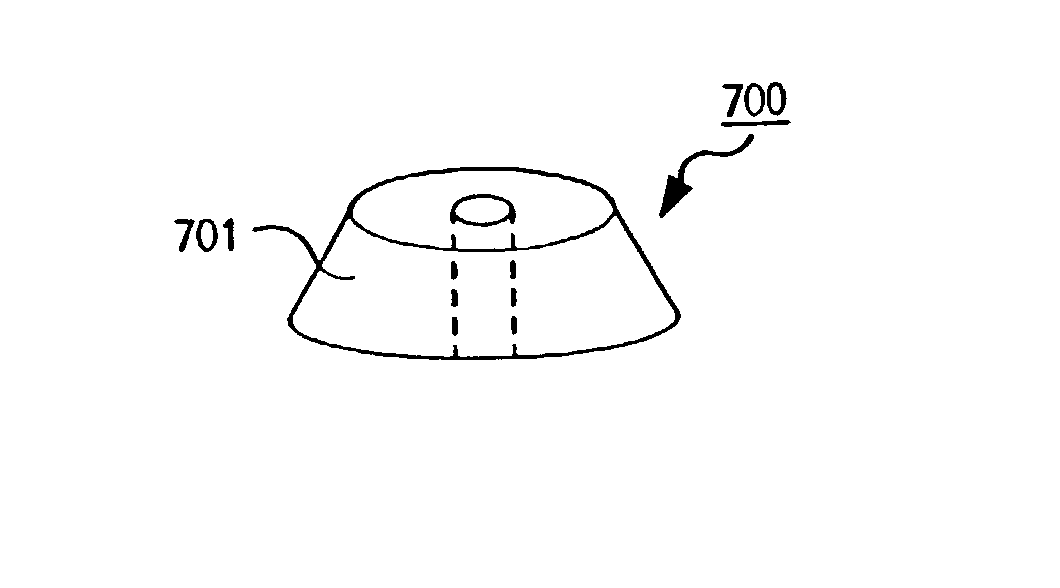
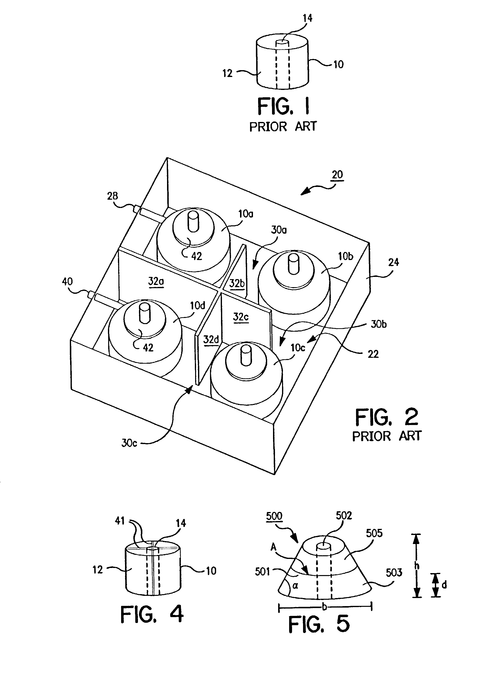
[0057]FIG. 5 is a perspective view of a dielectric resonator in accordance with the present invention. As shown, the resonator 500 is formed in-the shape of a truncated cone 501 with a central longitudinal through hole 502. The conical shape physically separates the TE mode field from the H11 mode field. As in the prior art, the primary purpose of the through hole is to suppress the Transverse Magnetic (TM) mode, which is another dangerous, spurious mode. The TM mode is the only mode not affected by the conical shape of the resonator in accordance with the present invention. Its frequency may be near the TE mode frequency. Therefore, the through hole in the conical resonators in accordance with the present invention should be designed with the appropriate diameter to completely suppress the TM mode.

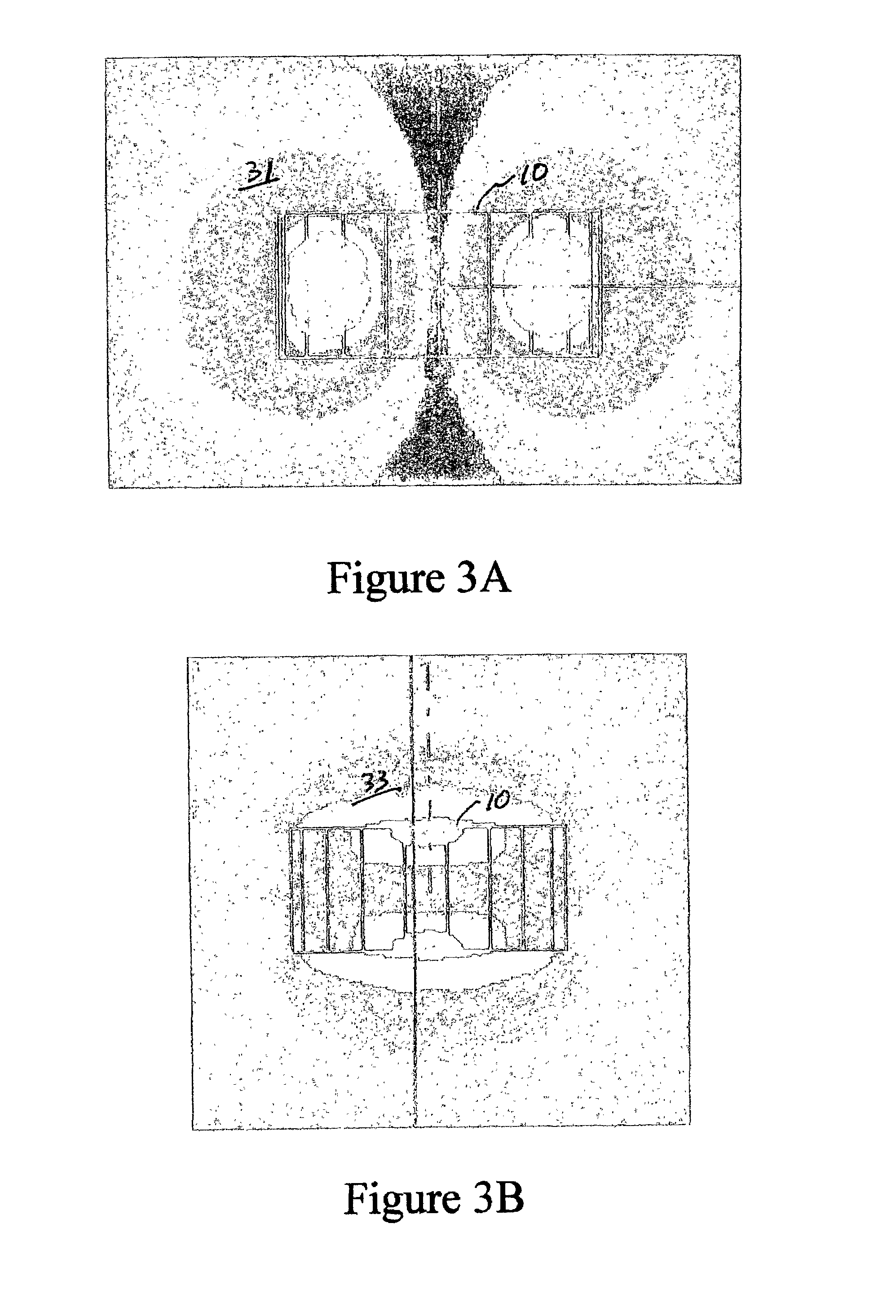
[0058]Referring to FIGS. 6A and 6B, the TE mode electric field 504FIG. 6A) tends to concentrate in the base 503 of the resonator because of the transversal components of the electric fiel...


PUM


Abstract

A dielectric resonator having variable cross-section, preferably varying monotonically, and, most preferably, the resonator being in the shape of a truncated cone. Such shapes displace the H11 mode from the TE mode in the longitudinal direction of the cone. Truncating the cone to eliminate the portion of the cone where the H11 mode exists, virtually eliminates the H11 mode. A circuit comprising a plurality of these resonators may be arranged in an enclosure with each resonator longitudinally inverted relative to adjacent resonator(s) to provide a compact design with enhanced coupling and adjustability. A spiral coupling loop provides high magnetic flux in a small physical volume for coupling energy into or out of the circuit. Alternately, the resonator can coupled to a microstrip by placing the resonator upside-down near the microstrip, whereby the TE mode is immediately above the microstrip, providing enhanced coupling there between.

Description

RELATED APPLICATION[0001]This application claims the benefit of U.S. Provisional Application entitled “Dielectric Resonators and Circuits Made Therefrom,” filed Sep. 17, 2002, Application No. 60 / 411,337.FIELD OF THE INVENTION[0002]The invention pertains to dielectric resonators, such as those used in microwave circuits for concentrating electric fields, and to the circuits made from them, such as microwave filters, oscillators, triplexers, antennas etc.BACKGROUND OF THE INVENTION[0003]Dielectric resonators are used in many circuits, particularly microwave circuits, for concentrating electric fields. They can be used to form filters, oscillators, triplexers and other circuits. The higher the dielectric constant of the dielectric material out of which the resonator is formed, the smaller the space within which the electric fields are concentrated. Suitable dielectric materials for fabricating dielectric resonators are available today with dielectric constants ranging from approximatel...

Claims


Application Information

Patent Timeline
Patent Type & Authority Patents(United States)
IPC IPC(8): H01P7/10H01P1/162H01P1/207H01P1/208
CPCH01P1/162H01P7/105H01P1/2084H01P1/207
Inventor PANCE, KRISTI DHIMITERCHANNABASAPPA, ESWARAPPA
Owner COBHAM DEFENSE ELECTRONICS SYST CORP
Why Eureka
Try Eureka