Method of analyzing ligand in sample and apparatus for analyzing ligand in sample

a technology of ligand and sample, which is applied in the field of method an apparatus for analyzing a ligand in a sample, can solve the problems of significant deterioration in reading precision and difficulty in producing portable apparatuses suitable for these methods, and achieve high-precision analysis

Inactive Publication Date: 2007-12-25
PANASONIC CORP
View PDF8 Cites 11 Cited by
  • Summary
  • Abstract
  • Description
  • Claims
  • Application Information

AI Technical Summary

Benefits of technology

[0011]As described above, in the analyzing method and apparatus of the present invention, external vibration is applied, and the frequency characteristics of a surface plasmon resonance angle with respect to the external vibration are obtained. Due to the external vibration, a dielectric constant in a vicinity of the metal thin film is changed. The dielectric constant change causes a change in the surface plasmon resonance angle. Thus, the analyzing method and apparatus of the present invention measures the frequency characteristics of the surface plasmon resonance angle. Therefore, it is not necessary to measure a minute change in the surface plasmon resonance angle. As a result, it is possible to achieve high-precision analysis without being affected significantly by vibration and optical design. In addition, the apparatus of the present invention can resist vibration, and therefore, can be miniaturized.

Problems solved by technology

In addition, since a minute change is detected, reading precision deteriorates significantly when an apparatus suffers from vibration during measurement.
Therefore, it is difficult to produce portable apparatuses that are suitable for these methods.Non-patent document 1: Anal. Chem., 1998, 70,2019-2024Patent document 1: JP 2003-65947 APatent document 2: JP 2003-75336 A

Method used


Image

  • Method of analyzing ligand in sample and apparatus for analyzing ligand in sample
  • Method of analyzing ligand in sample and apparatus for analyzing ligand in sample
  • Method of analyzing ligand in sample and apparatus for analyzing ligand in sample

Examples


first embodiment

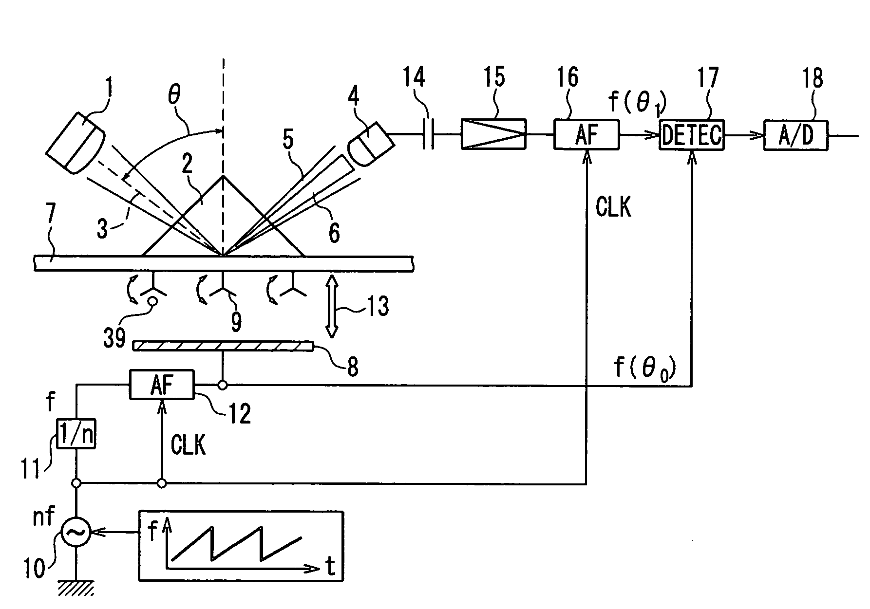
[0027]In a first embodiment of the present invention, a preferable embodiment of the apparatus of the present invention will be described. FIG. 1 is a schematic diagram illustrating an example of the apparatus of the present invention. In FIG. 1, 1 indicates a light source, 2 indicates a prism, 3 indicates measuring light. 4 indicates a light receiving apparatus. 5 indicates reflected light. 6 indicates a reflected light dark portion in which the amount of light is partially reduced due to excitation of plasmon. 7 indicates a metal thin film and upper electrode. 8 indicates a lower electrode. 9 indicates a receptor immobilized on the metal film and upper electrode 7. 10 indicates an alternating current source. 11 indicates a frequency divider that divides a frequency of the alternating current source 10. 12 and 16 each indicate an active filter that passes only a specific frequency. 13 indicates external vibration. 14 indicates a capacitor. 15 indicates an amplifier. 17 indicates a ...

second embodiment

[0052]In a second embodiment, another preferable embodiment of the apparatus of the present invention will be described. In FIG. 7, 51 indicates a light source. 52 indicates a receptor immobilized on a metal film and upper electrode. 53 indicates a ligand. 54 indicates a light receiving apparatus. 56 indicates a metal thin film and electrode. 58 indicates a reflector. 59 indicates an electrode. 60 indicates an alternating current source. 61 indicates a frequency divider that divides a frequency of the alternating current source 60. 62 and 66 each indicate an active filter that passes a specific frequency. 55 indicates an external vibration. 64 indicates a capacitor. 65 indicates an amplifier. 67 indicates a detector that compares a phase (θ0) of external vibration and a phase (θ1) of a signal component of external vibration included in reflected light. 68 indicates an A / D converter that converts an analog signal obtained by the detector 67 into a digital signal. 70 indicates measuri...


PUM

PropertyMeasurementUnit
dielectric constantaaaaaaaaaa
pHaaaaaaaaaa
pHaaaaaaaaaa

Abstract

A sample analyzing method capable of high-precision analysis without being affected by vibration and optical design is provided. In the sample analyzing method, a sample containing a ligand is caused to bind to a receptor that can bind specifically to the ligand, and a change caused by binding of the receptor and the ligand is analyzed by measuring frequency characteristics of a surface plasmon resonance angle while applying external vibration to the receptor. The sample analyzing method is useful in the fields of, for example, biology, medicine, pharmacology, agriculture, and the like.

Description

TECHNICAL FIELD[0001]The present invention relates to a method for analyzing a ligand in a sample and an apparatus for analyzing a ligand in a sample.BACKGROUND ART[0002]Among biochemical reactions, the reaction of binding a receptor and a ligand is important. For example, in an antigen-antibody reaction, an antibody as a receptor binds to an antigen as a ligand. For example, in an enzymatic reaction, an enzyme as a receptor binds to an enzyme substrate as a ligand. By utilizing these reactions, a ligand present in a sample can be detected.[0003]For example, a receptor is bound to a metal thin film surface. When a ligand binds to the receptor, the dielectric constant in the vicinity of the metal thin film is changed. A method of using a surface plasmon resonance phenomenon to detect such a change and thereby analyze the amount of a receptor-ligand complex, has been known (see, for example, Non-patent document 1). In this method, initially, a metal thin film to whose surface a recept...

Claims


Application Information

Patent Timeline
Patent Type & Authority Patents(United States)
IPC IPC(8): G01N33/553G01N21/55
CPCG01N21/553Y10S436/805Y10S436/817Y10S435/808
Inventor BAN, TOMOAKIKIRINO, HIDEKI
Owner PANASONIC CORP
Why Eureka
Try Eureka