Atmosperic pressure quadrupole analyzer

a quadrupole analyzer and atmospheric pressure technology, applied in the direction of instruments, particle separator tube details, separation processes, etc., can solve the problems of affecting deleteriously the motion of ions, limiting the operating pressure, and transferring small amounts of translational energy between, so as to achieve precise band-pass capability

Inactive Publication Date: 2007-12-25
CHEM SPACE ASSOIATES
View PDF36 Cites 38 Cited by
  • Summary
  • Abstract
  • Description
  • Claims
  • Application Information

AI Technical Summary

Benefits of technology

[0032](f) to provide a RF/DC mass and mobility analyzer with an a

Problems solved by technology

This results in the transfer of small amounts of translational energy between the different dimensions.
But there are limits with the operating pressures.
In addition, scattering effects from discrete collisions between ions and the surrounding gases deleteriously affect the motion of the ions in the intermediate pressure region as well.
Although these ion trapping devices may be able to trap ions, but once the ions are trapped ejecting the ions from the trap is very difficult due to lack of inertia of the ions at higher pressures, especially at, near, and above atmospheric pressure.
(a) Conventional quadrupole mass filters require the need for components, such as vacuum chambers, high-vacuum electrical feed-throughs, etc., that can withstand large pressure differences (−1,000 torr). This necessitates the need for stainless steel, aluminum, or other materials; chambers with vacuum tight welds; or metal or rubber seals that can withstand the large pressure difference.
(b) Conventional quadrupole mass filters require the need for expensive high vacuum pumps, such as turbomolecular or diffusion pumps; and low vacuum pumps, such as mechanical vane pumps; both costing several thousands of dollars. The cost of these pumps can makeup approximately 20% of the total cost of an instrument.
(c) Atmospheric interfaces for quadrupole mass filters require expensive high vacuum pumps for operation, resulting in costly and complex interface desi

Method used


Image

  • Atmosperic pressure quadrupole analyzer
  • Atmosperic pressure quadrupole analyzer
  • Atmosperic pressure quadrupole analyzer

Examples


Embodiment Construction

Preferred Embodiment—FIGS. 6A, 6B, 7, 8, 9A, and 9B (Basic Focusing Device, On-Axis Detection)

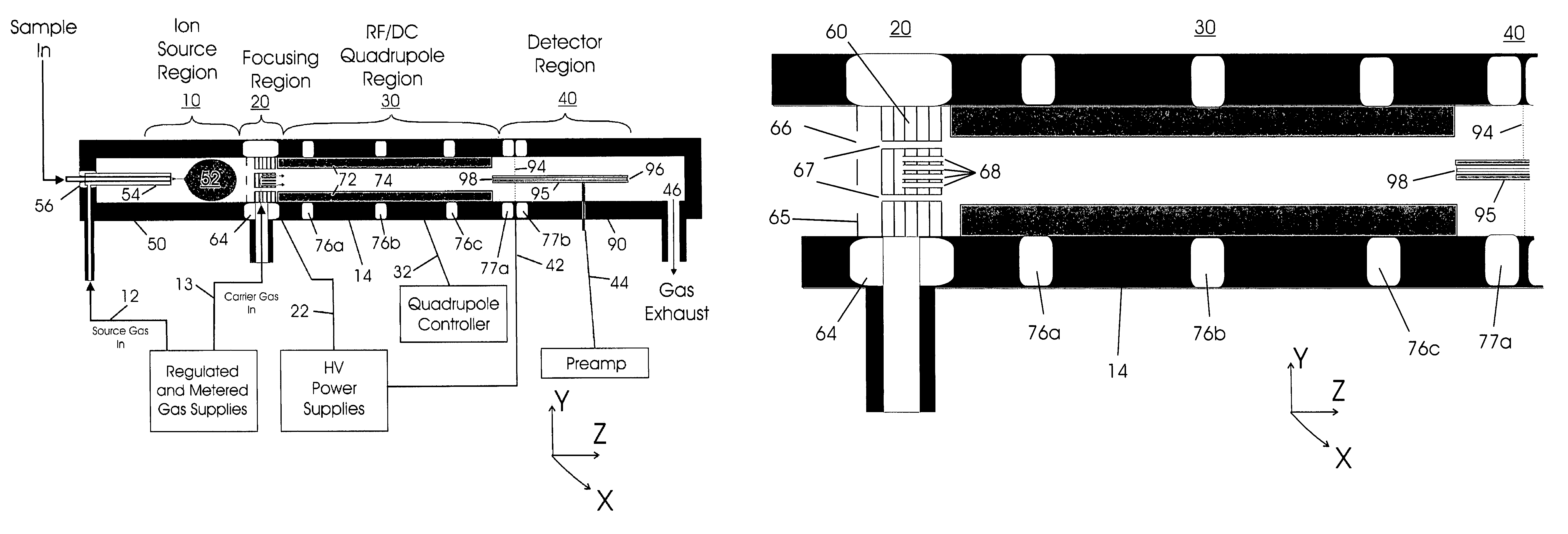
[0109]A preferred embodiment of the atmospheric RF / DC device of the present invention is illustrated in FIGS. 6A and 6B. Basic parts include an Ion Source Region 10, Focusing Region 20, RF / DC Quadrupole Region 30, and Detector Region 40. The Ion Source Region 10 is mounted at one end of the cylindrical electrically conductive analyzer housing 14 and is symmetrically disposed about the central axis Z. The ion source may comprise, for example, a conductive electrospray ionization chamber 50 comprised of an ionization region 52, an electrospray needle 54, an insulator 56, and a gas inlet 12. A carrier gas is supplied upstream of the Ion Source Region 10 through the gas inlet 12 from the regulated and metered gas supply source. The gas is generally composed of, but not limited to nitrogen.

[0110]This device is intended for use in collection and focusing of ions from a wide variety of ion sources...


PUM


Abstract

The present invention relates to an apparatus and method for focusing, separating, and detecting gas-phase ions using the principles of electrohydrodynamic quadrupole fields at high pressures, at or near atmospheric pressure. Ions are entrained in a concentric flow of gas and travel through a high-transmission element into a RF/DC quadrupole, exiting out of the RF/DC quadrupole, and then impacting on an ion detector, such as a faraday plate; or through an aperture or capillary tube with subsequent identification by a mass spectrometer. Ions with stable trajectories pass through the RF/DC quadrupole while ions with unstable trajectories drift off-axis collide with the rods and are lost. Alternatively, detection of ions with unstable trajectories can be accomplished by allowing the ions to pass through the rods and be detected by an off-axis detector. Embodiments of this invention are devices and methods for focusing, separating, and detecting gas-phase ions at or near atmospheric pressure, when coupled to mass spectrometers.

Description

GOVERNMENT SUPPORT[0001]The invention described herein was made in part with United States Government support under Grant Number: 1 R43 RR15984-01 from the Department of Health and Human Services. The U.S. Government may have certain rights to this invention.CROSS-REFERENCE TO RELATED APPLICATION[0002]This application is entitled to the benefit of application Ser. No. 10 / 155,151, filed 2001 May 26, now U.S. Pat. No. 6,784,424, issued 2004 Aug. 31. In addition, this invention uses the high-transmission elements of our applications, Ser. No. 09 / 877,167, filed 2001 Jun. 8, now U.S. Pat. No. 6,744,041, issued 2004 Jun. 1; and Ser. No. 10 / 449,147, filed 2003 May 31, now U.S. Pat. No. 6,818,889, issued 2004 Nov. 16; Ser No. 10 / 862,304, filed 2003 Jun. 7, now U.S. patent publication No. 2005 / 0056776, issued 2005 Mar. 17; and Ser. No. 10 / 989,821, filed 2004 Nov. 15.BACKGROUND[0003]1. Field of Invention[0004]This invention relates to an atmospheric RF / DC device, specifically to such RF / DC de...

Claims


Application Information

Patent Timeline
IPC IPC(8): H01J49/26B01D59/44H01J49/16
CPCH01J49/065H01J49/24H01J49/4215
Inventor WILLOUGBHY, ROSS CLARKSHEEHAN, EDWARD WILLIAM
Owner CHEM SPACE ASSOIATES
Why Eureka
Try Eureka