Sintered wire anode

a technology of sintered wire and anode, which is applied in the direction of x-ray tube target materials, x-ray tube targets, convertors, etc., can solve the problems of material buckle or warp, material size and distribution of pores can be optimized, and improve the operating characteristics, including cathode emission density and lifetime.

Inactive Publication Date: 2007-12-25
CALABAZAS CREEK RES
View PDF15 Cites 10 Cited by
  • Summary
  • Abstract
  • Description
  • Claims
  • Application Information

AI Technical Summary

Benefits of technology

[0033]The present invention describes a technique which allows for controlled, uniform distribution of pores over the entire cathode surface. The technique does not require that the emission material be impregnated, but instead uses a reservoir of work function reducing material below the surface that can provide substantially improved cathode lifetime before the impregnate is depleted. The precise control of both the pore size and uniform electron distribution will allow custom design of the cathode for specific applications.
[0034]It is the primary object of the present invention to provide a method for fabricating a dispenser cathode having a uniform surface porosity so that uniform electron emission can be achieved.
[0037]The process can be used to control the size of the pores, which can affect the rate of migration of the impregnate, and the distribution of the pores over the surface. The size and distribution of the pores can be optimized based on the application of the cathode to improve the operating characteristics, including the cathode emission density and lifetime.

Problems solved by technology

Accordingly, dispenser cathodes of the prior art do not have uniform surface electron emission.
This technique would not be applicable to large cathodes where differential thermal expansion could cause the material to buckle or warp.
Thereafter an array of apertures is formed in the end wall of the housing by laser drilling to create an emitter-dispenser, but this method is only applicable to small cathodes, as the laser drilling process becomes unmanageable for large cathodes where millions of holes would be required.
Also, the thin coating which forms the emitter is subject to warping and buckling from differential expansion of the coating and the support structure.
This process also includes a large number of separate sequential processes to obtain the final cathode and can not provide cathode emitting surfaces of arbitrary thickness.
This results in non-uniform distribution of the work function reducing impregnate over the surface 16.
Problems occur when the distribution of pores varies across the cathode surface, leading to nonuniform migration of the impregnate.
This is particularly troublesome for cathodes operating in a regime where the emission is dependent on the temperature.

Method used


Image

  • Sintered wire anode
  • Sintered wire anode
  • Sintered wire anode

Examples


Embodiment Construction

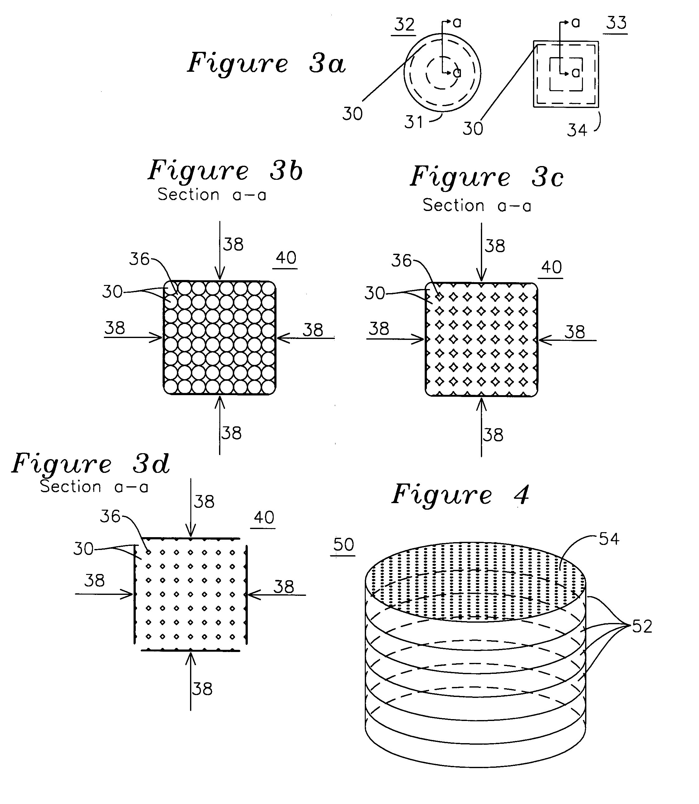
[0055]FIG. 3a shows a round bobbin 31 having tungsten wire 30 wound around it, or alternatively a square bobbin 33 having been wound with tungsten wire 30. The wire 30 may be formed from any material or diameter, however it is believed that tungsten wire with a fixed diameter in the range 10-20u is preferred for porous dispenser cathodes. Tungsten wire in this diameter range is commonly available for use in electro-discharge machining (EDM) and is also used as a source material for fabricating the filament of an incandescent light bulb. When wound about a square 34 or circular 31 bobbin, the cross section a-a of a bundle of such tungsten wires appears as shown in FIG. 3b. While the axial wire 30 tension from winding on the bobbin naturally causes a radial confining force, it may be desired to supplement this tensile force with external confining force 38 to enable uniform wire 30 packing during sintering. The porous cathode structure is formed from a plurality of sintered tungsten w...


PUM

PropertyMeasurementUnit
temperatureaaaaaaaaaa
thicknessaaaaaaaaaa
temperaturesaaaaaaaaaa

Abstract

A plurality of high atomic number wires are sintered together to form a porous rod that is parted into porous disks which will be used as x-ray targets. A thermally conductive material is introduced into the pores of the rod, and when a stream of electrons impinges on the sintered wire target and generates x-rays, the heat generated by the impinging x-rays is removed by the thermally conductive material interspersed in the pores of the wires.

Description

[0001]This application is a continuation-in-part of pending application Ser. No. 11 / 085,425 filed on Mar. 21, 2005.[0002]This invention was made with United States government support under Grant DE-FG-03-04ER83918 from the United States Department of Energy. The United States Government has certain rights in this invention.FIELD OF THE INVENTION[0003]The present invention is related to porous cathode structures for use with microwave tubes, linear beam devices, linear accelerators, cathode ray tubes, x-ray tubes, ion lasers, and ion thrusters. More particularly, it is related to a dispenser cathode which is fabricated from a plurality of wires which are sintered into a porous cathode structure which is then parted into a porous cathode disk. The dispenser cathode is formed by bonding the porous cathode disk to a cathode enclosure proximal to both a heater and a source of work-function reducing material such as BaO, CaO, or Al2O3, which migrates through the pores of the porous cathod...

Claims


Application Information

Patent Timeline
Patent Type & Authority Patents(United States)
IPC IPC(8): H01J35/08
CPCH01J35/06H01J35/08H01J2235/081H01J2235/06H01J35/112H01J35/064
Inventor FALCE, LOUIS R.IVES, R. LAWRENCE
Owner CALABAZAS CREEK RES
Why Eureka
Try Eureka