Cutting insert and use thereof

a cutting insert and cutting technology, applied in the field of cutting inserts, can solve the problems of low transverse rupture strength of ceramic cutting inserts, inability to manufacture useful indexable inserts made of solid cemented carbide, and inability to manufacture tools from high-temperature resistant ceramics. , to achieve the effect of small cutoff width, excellent suitability of cutting inserts, and high mechanical stiffness of composite structures

Inactive Publication Date: 2008-01-01
KENNAMETAL INC
View PDF38 Cites 21 Cited by
  • Summary
  • Abstract
  • Description
  • Claims
  • Application Information

AI Technical Summary

Benefits of technology

[0009]Accordingly, one possible object of the present invention is to provide cutting inserts which are particularly suitable for high-speed metal cutting operations, that is, are especially heat-resistant, while nonetheless exhibiting a very high mechanical strength, so that even very small cutting bodies having a very small cutoff width or a very small radius can be manufactured which have a sufficient tool life.SUMMARY
[0011]In the cutting insert in accordance with one possible embodiment, the high-temperature characteristics of a ceramic cutting body are combined with the advantages of a carrier of solid cemented carbide. The special mutual matching of the geometric shape of the ceramic cutting body, which is configured in the nature of a male mold, and the geometric shape of the recess in the cemented carbide insert, formed in the nature of a female mold adapted thereto, results in a high mechanical stiffness of the composite structure formed of the two bodies, which has an advantageous effect in particular in high-speed machining of workpieces associated with high and extremely high temperatures.
[0013]Preferably, the ceramic cutting body has a smaller base surface which is attached to the bottom of the recess, while the cutting edge is formed at the exposed circular arc of the larger base surface of the circular truncated cone and extends in the shape of a partial circle. This design results in an optimum ratio between rake faces and flank faces and, hence, an excellent suitability of the cutting insert for the manufacture of indexable inserts which have many uses and are in particular suitable for tools having a very small cutoff width or a very small radius.
[0017]In a preferred embodiment of the cutting insert, at least one groove extending transversely to the longitudinal axis of the cutting insert is provided for fastening the cutting insert to a conventional toolholder. In order to attain a substantially immovable, geometrically precisely definable seating of the cutting insert in a toolholder provided therefor, it is advantageous if the at least one groove is defined on either side by raised portions extending parallel to the groove, so as to allow a positive engagement with the fastening means provided therefor of the toolholder.

Problems solved by technology

While ceramic cutting inserts are basically more suitably used for high-temperature applications, i.e. for metal cutting of workpieces in the high-speed range, than cemented carbide cutting inserts, the lower transverse rupture strength of the ceramic cutting inserts becomes noticeable increasingly more negatively as the dimensions of the cutting inserts become smaller.
For this reason it had so far not been possible to manufacture tools from a high-temperature resistant ceramic material which have a very small cutoff width or a very small radius for copy-turning in the high-speed range.
On the other hand, it had so far not been possible to manufacture useful indexable inserts made of solid cemented carbide and having very small dimensions and simultaneously highly complex shapes.

Method used


Image

  • Cutting insert and use thereof
  • Cutting insert and use thereof

Examples


Embodiment Construction

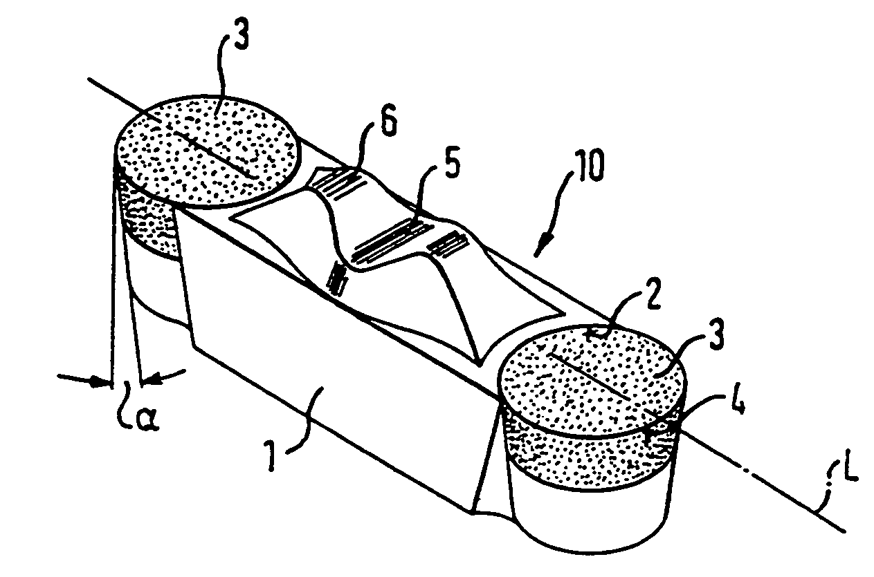
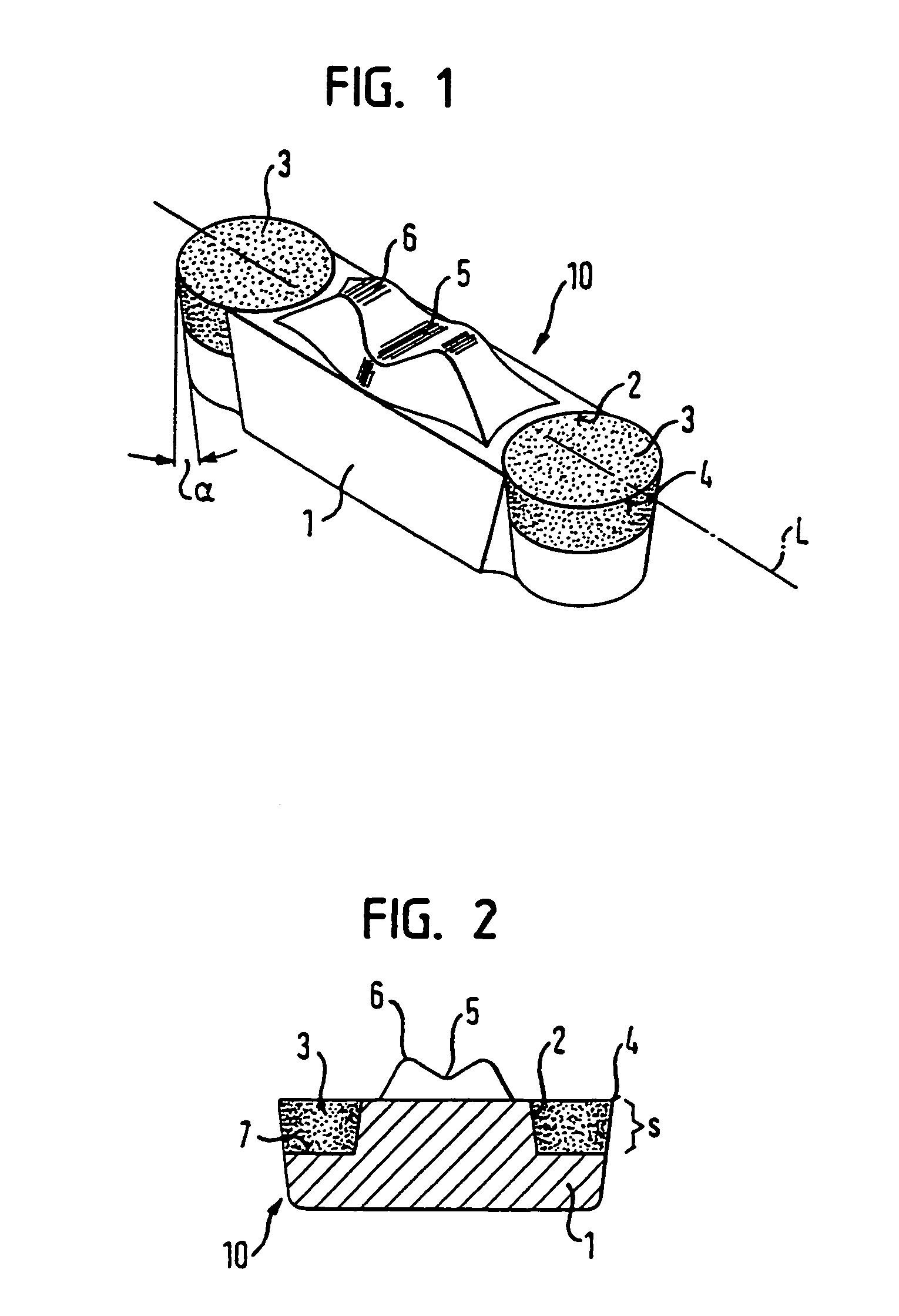
[0025]The cutting insert 10 comprises a base body 1 made of cemented carbide (cobalt-bound tungsten carbide), the cutting insert being designed as an indexable insert having a pair of ceramic cutting bodies 3.

[0026]The two ceramic cutting bodies 3 have the shape of a perpendicular circular truncated cone and are bonded into preformed recesses 2 of the base body 1 by means of a high-temperature adhesive in such a way that the smaller base surface of the circular truncated cone is bonded firmly to the bottom 7 of the recess and a part of the conical shell surface of the circular truncated cone to the conical wall surface congruent therewith of the recess2. A cutting edge 4 is formed on the exposed circular arc of the larger base surface of the circular truncated cone of each of the two ceramic cutting bodies 3. The exposed partial circle, i.e., not extending within the recess 2, of the larger base surface of the circular truncated cone comprises at least 200°, but not more than 230° (...


PUM

PropertyMeasurementUnit
diameteraaaaaaaaaa
clearance angleaaaaaaaaaa

Abstract

A cutting insert made of cemented carbide and the use thereof for recessing or copy-turning, preferably at a high rotating speed. The cutting insert has at least one recess for insertion therein of a cutting body of a material other than cemented carbide, such as a ceramic material.

Description

[0001]This application is a Continuation-In-Part application of International Patent Application No. PCT / IB02 / 03374, filed on Aug. 21, 2002, which claims priority from Federal Republic of Germany Patent Application No. 101 42 049.8, filed on Aug. 28, 2001. International Patent Application No. PCT / IB02 / 03374 was pending as of the filing date of this application. The United States was an elected state in International Patent Application No. PCT / IB02 / 03374.BACKGROUND[0002]1. Technical Field[0003]The present application relates to a cutting insert made of cemented carbide having at least one recess for insertion therein of a cutting body consisting of a cutting material different from cemented carbide to form a firm connection, the cutting body having formed a cutting edge thereon.[0004]2. Background Information[0005]Cutting inserts of this type are known from U.S. Pat. Nos. 3,369,283 and 4,201,501 and from EP-B1-0 431 009, for example.[0006]These prior cutting inserts consist of a ceme...

Claims


Application Information

Patent Timeline
Patent Type & Authority Patents(United States)
IPC IPC(8): B23B27/18B23B27/14B23B27/06
CPCB23B27/06B23B2220/12B23B2222/28B23B2226/18Y10T407/26B23B2240/21B23B2265/34Y10T407/23Y10T82/10B23B2240/08
Inventor PENKERT, WERNER
Owner KENNAMETAL INC
Why Eureka
Try Eureka