Lanthanide-halide based humidity indicators

a humidity indicator and lanthanide halide technology, applied in the field of visual humidity indicators, can solve the problems of poor indicating extremely low relative humidity levels (i.e. below 5%) at common ambient temperatures, affecting the quality of pharmaceuticals or destabilizing munitions, and poor lanthanide halide based humidity indicators work well, and achieve the effect of cost effectiveness

Inactive Publication Date: 2008-01-01
THE UNITED STATES AS REPRESENTED BY THE DEPARTMENT OF ENERGY
View PDF13 Cites 8 Cited by
  • Summary
  • Abstract
  • Description
  • Claims
  • Application Information

AI Technical Summary

Benefits of technology

[0015]An advantage of the present invention is its ability to overcome the problems associated with prior art humidity indicators;
[0016]Another advantage of the present invention is its ability to detect very small amounts of water vapor.
[0017]Yet another advantage of the present invention is its ability to undergo multiple hydration / rehydration cycles at ambient temperatures while maintaining its ability to detect humidity levels.
[0018]Another advantage of the present invention is that it is non-carcinogenic;
[0019]Still another advantage of the present invention is its cost effectiveness for high volume applications.
[0020]Yet another advantage of the present invention is the speed in which it indicates a rise in humidity.

Problems solved by technology

Even small amounts of humidity can corrode a semi-conductor, effect the quality of pharmaceuticals or destabilize munitions.
Cobalt salt indicators work well in moderate humidity levels but they are poor at indicating extremely low relative humidity levels (i.e. below 5%) at common ambient temperatures.
This makes the use of cobalt chloride-based indicators undesirable.
Deliquescent indicators work in some situations, but their low heat resistance and tendency to undergo irreversible chemical change limit their potential use.
Electronic humidity indicators have become more prevalent in recent years but they are not cost-effective for high volume applications.

Method used


Image

  • Lanthanide-halide based humidity indicators
  • Lanthanide-halide based humidity indicators
  • Lanthanide-halide based humidity indicators

Examples


example 1

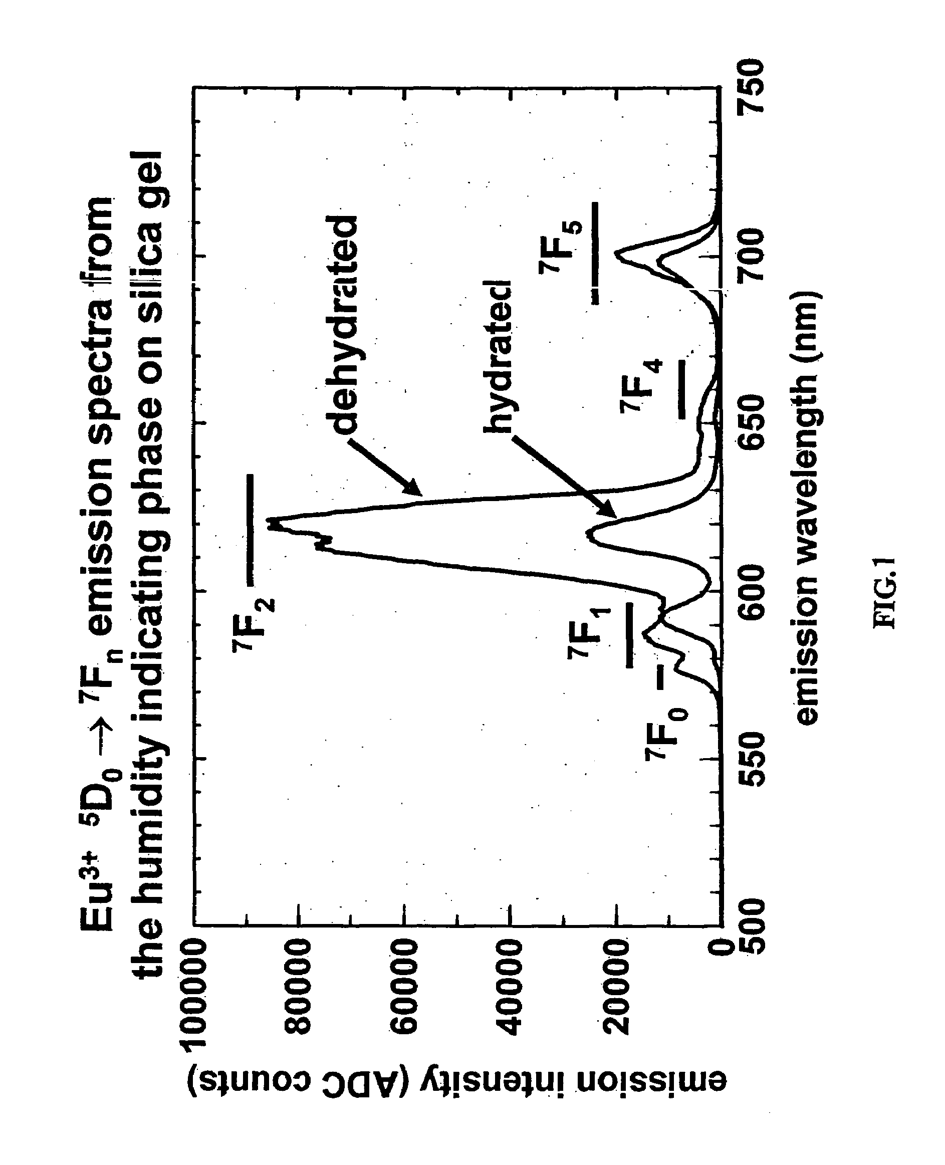
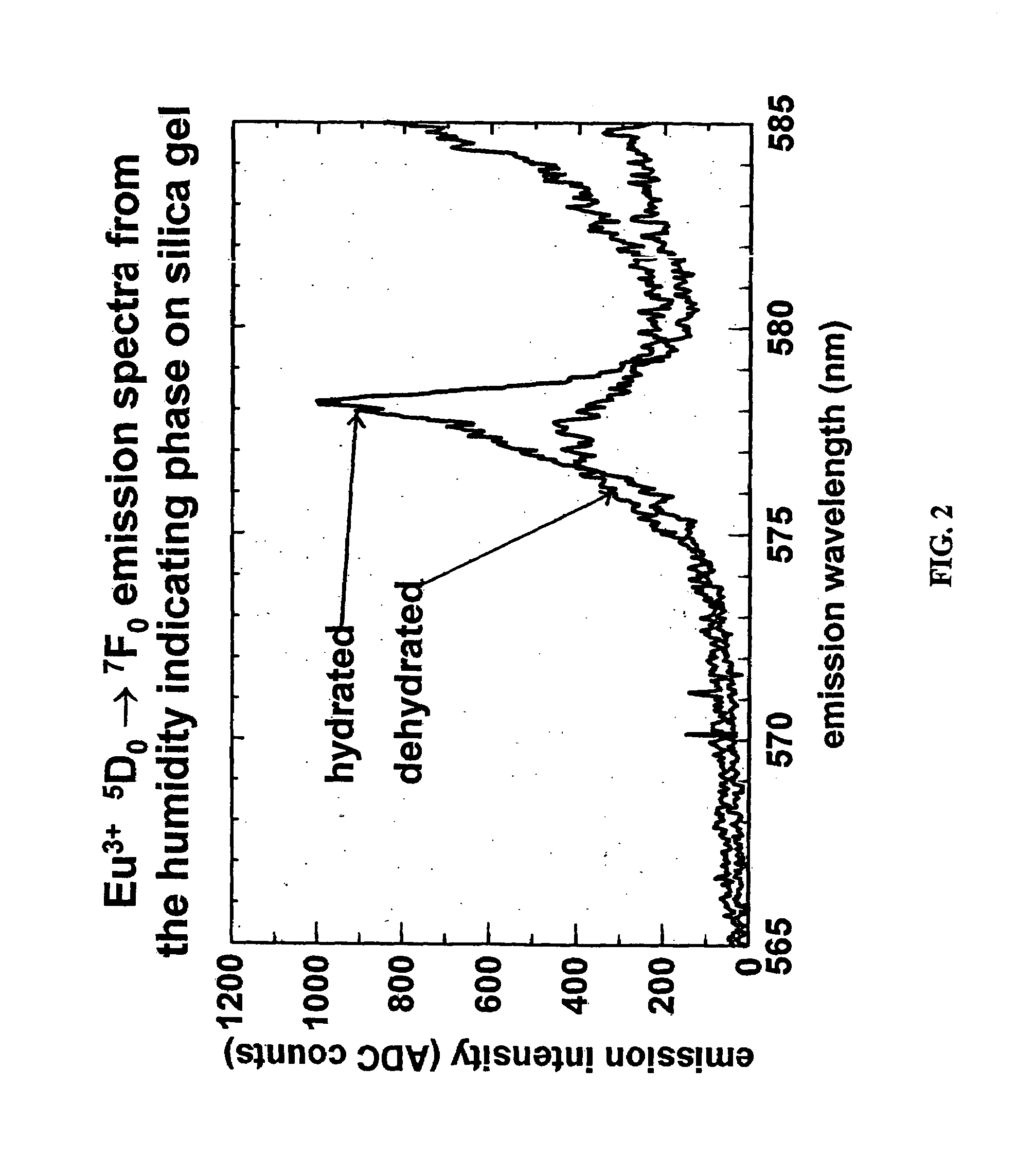
[0055]An aqueous hydrobromic acid solution (HBr) (containing dissolved free bromine) was formed by mixing liquid bromine (Br2) with aqueous hydrobromic acid (˜48% hydrogen bromide by weight) in an amount sufficient to from a solution with an optical density of 0.90 per cm of optical pathlength at 500 nanometers. 3.34 g of the prepared hydrobromic acid-free bromine solution was mixed with 0.28 g of europium sesquioxide (Eu2O3) and the solution was mixed until the Eu2O3 was dissolved forming a europium-bromide mixture. 2.40 g of water was added to the europium-bromide mixture forming a europium-bromide-water solution. 1.10 g of ammonium bromide (NH4Br) was mixed with the europium-bromide-water mixture to give a humidity indicating solution. 1.15 ml of the humidity indicating solution was added dropwise to 1.00 g of porous, high surface area silica gel. The sorbed silica gel was then dried under nitrogen gas flow until it turned yellow indicating its anhydrous state.

[0056]The present i...


PUM

PropertyMeasurementUnit
temperaturesaaaaaaaaaa
humidityaaaaaaaaaa
temperatureaaaaaaaaaa

Abstract

The present invention discloses a lanthanide-halide based humidity indicator and method of producing such indicator. The color of the present invention indicates the humidity of an atmosphere to which it is exposed. For example, impregnating an adsorbent support such as silica gel with an aqueous solution of the europium-containing reagent solution described herein, and dehydrating the support to dryness forms a substance with a yellow color. When this substance is exposed to a humid atmosphere the water vapor from the air is adsorbed into the coating on the pore surface of the silica gel. As the water content of the coating increases, the visual color of the coated silica gel changes from yellow to white. The color change is due to the water combining with the lanthanide-halide complex on the pores of the gel.

Description

U.S. GOVERNMENT RIGHTS[0001]The United States Government has rights in this invention pursuant to Contract No. W-31-109-ENG-38 between the U.S. Department of Energy and the University of Chicago, representing Argonne National Laboratory.TECHNICAL FIELD[0002]The present invention relates to a visual humidity indicator. Specifically, the invention relates to a reusable lanthanide-halide based humidity indicator that changes colors in the presence of minute amounts of water vapor.BACKGROUND OF THE INVENTION[0003]The maintenance of extremely low humidity environments is critical to a number of industries including: electronics manufacturing, (i.e. semi-conductors), pharmaceuticals, munitions storage, and specialty packaging. For example, the semi-conductor industry ships some of its products in extremely low humidity packaging (less than 5% relative humidity) to prevent corrosion. Even small amounts of humidity can corrode a semi-conductor, effect the quality of pharmaceuticals or desta...

Claims


Application Information

Patent Timeline
Patent Type & Authority Patents(United States)
IPC IPC(8): G01N33/00G01N31/00
CPCG01N31/222
Inventor BEITZ, JAMES V.WILLIAMS, CLAYTON W.
Owner THE UNITED STATES AS REPRESENTED BY THE DEPARTMENT OF ENERGY
Why Eureka
Try Eureka