Volume coil for a magnetic resonance tomography apparatus

a volume coil and tomography technology, applied in the field of radiofrequency volume coils for tomography apparatus, can solve the problems of reducing the signal/noise ratio, disadvantageous that these volume coils each have a fixed size, and the volume coil arrangement is not suitable for measurements with a stereotaxic frame, so as to achieve a better signal/noise ratio

Inactive Publication Date: 2008-01-01
SIEMENS AG
View PDF6 Cites 24 Cited by
  • Summary
  • Abstract
  • Description
  • Claims
  • Application Information

AI Technical Summary

Benefits of technology

[0013]An object of the present invention is to avoid the aforementioned disadvantages of the prior art and to provide a volume coil of variable size with which measurements of heads of different sizes as well as measurements of heads with stereotaxic frames can be conducted. The invention is not limited to volume coils that are used in the head region of a patient, since volume coils with variable internal cross-section can be advantageously used everywhere that a better signal / noise ratio can be achieved by an adaptation of the cross-section of the volume coil to the contours of the measurement subject.

Problems solved by technology

In this technique it furthermore remains disadvantageous that these volume coils each has a fixed size.
In the latter case the internal volume of the coil must be so large that the stereotaxic frame still has space, which leads to the situation that measurements conducted in such a volume coil system on small or even large heads lead to signals with a reduced signal / noise ratio.
In reverse, if one makes the coil volume so small that good results are achieved given small or large heads, these volume coil arrangements are not suitable for measurements with a stereotaxic frame.

Method used


Image

  • Volume coil for a magnetic resonance tomography apparatus
  • Volume coil for a magnetic resonance tomography apparatus

Examples


Embodiment Construction

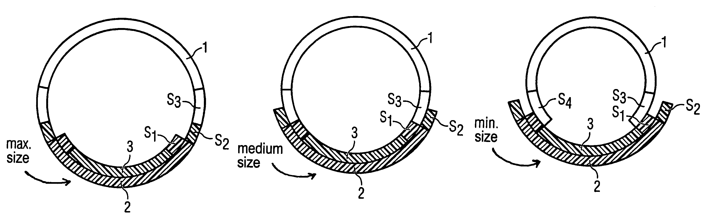
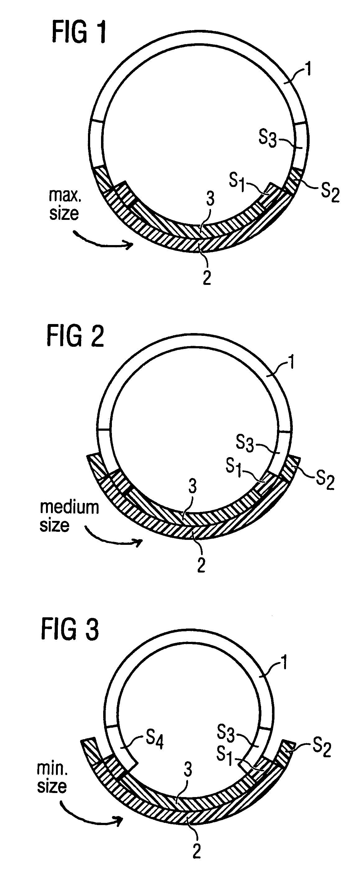
[0018]The volume coil shown in FIG. 1 has two coil carriers 1, 2 that, in the shown case, are each in the shape of circle segments and are arranged with their ends abutting one another. An annular volume coil arrangement is thereby generated. The coil carriers 1, 2 respectively carry array coil elements S1, S2, S3, S4 whose precise circuitry plays a subordinate role in the context of interest here, such that description thereof is not necessary. The lower coil carrier 2 in FIG. 1 additionally has a further carrier insert element 3 on its inner side (i.e. directed toward the center point of the ring). The carrier insert 3 describes a shorter circle segment than the length of the circle segment of the lower coil carrier 2. The inner carrier insert 3 likewise has array coil elements S1. It can be seen in FIG. 1 that the coil carrier 2 on both sides projects (by the width of the array coil element S2) beyond the front ends of the carrier inset 3. The coil elements S1, S2, S3 and S4 can ...


PUM


Abstract

A volume coil for a magnetic resonance (MR) tomography apparatus has a number of array coils or coil parts arranged on at least one coil carrier. The coil carrier annularly encloses or the coil carriers annularly encloses or enclose a cross-sectional area that can be varied by modifying the position of the coil carriers or parts thereof relative to one another.

Description

BACKGROUND OF THE INVENTION[0001]1. Field of the Invention[0002]The present invention concerns a radio-frequency volume coil for (MR) tomography apparatus.[0003]2. Description of the Prior Art[0004]A volume coil for MR tomography systems is known from DE 195 09 731 A1. Such volume coils are used in the gradient system of an MR scanner as RF transmission and / or reception coils. Radio-frequency fields for the excitation of the spins are generated and the generated signal is received. If the volume coil operates exclusively or also as a reception coil, its size (i.e. the size of the volume that the volume coil encloses) in relation to the size of the measurement subject plays a determining role for the resulting signal / noise ratio. An optimal signal / noise ratio is achieved when the volume coil is situated optimally close to the contour of the measurement subject.[0005]For this reason it is known in the prior art to implement examinations on the head of a patient with a special head vol...

Claims


Application Information

Patent Timeline
Patent Type & Authority Patents(United States)
IPC IPC(8): G01V3/00
CPCG01R33/34046G01R33/34084
Inventor BOTTCHER, UWE
Owner SIEMENS AG
Why Eureka
Try Eureka