
Dual dopant dual alpha multimode optical fiber

Active Publication Date: 2008-01-01
CORNING INC
View PDF6 Cites 106 Cited by
  • Summary
  • Abstract
  • Description
  • Claims
  • Application Information

AI Technical Summary

Benefits of technology

[0006]Multimode optical fiber is disclosed herein comprising germania (GeO2) and fluorine co-doped in the core of the fiber. The dopant concentration profiles are defined by a pair of alpha parameters, which in some embodiments may be equal to each other. The operating window, or bandwidth window, is enlarged and attenuation, or loss, is low. In some embodiments, two operating windows are available for transmission.
[0007]Each of the dual dopants, germania and fluorine, are disposed in the core of the multimode fiber in concentrations which vary with radius and which are defined by two alpha parameters, α1 and α2. That is, the germania dopant concentration varies with radius as a function of the alpha parameters, α1 and α2, as does the fluorine dopant concentration. The dual dopant concentrations disclosed herein also reduce the sensitivity with wavelength of the overall α shape of the refractive index of the optical fiber, which can help increase the productivity yield of such fibers during their manufacture, thereby reducing waste and costs. As used herein, the term graded index refers to a multimode optical fiber with a refractive index having an overall α of about 2.

Problems solved by technology

However, boron increases fiber attenuation, increasing the transmission losses of the MMF.

Method used


Image

  • Dual dopant dual alpha multimode optical fiber
  • Dual dopant dual alpha multimode optical fiber
  • Dual dopant dual alpha multimode optical fiber

Examples


example 1

Comparative

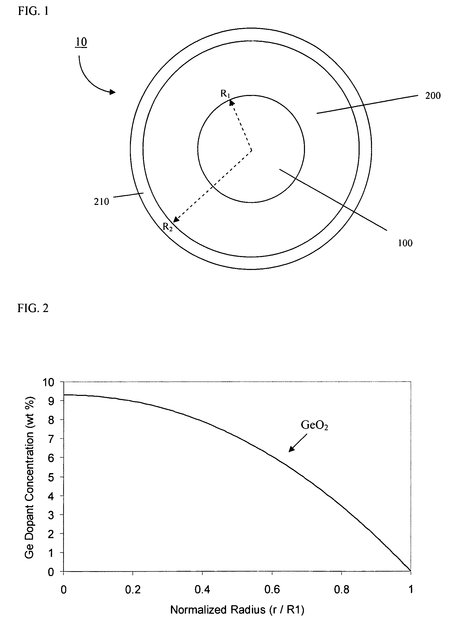
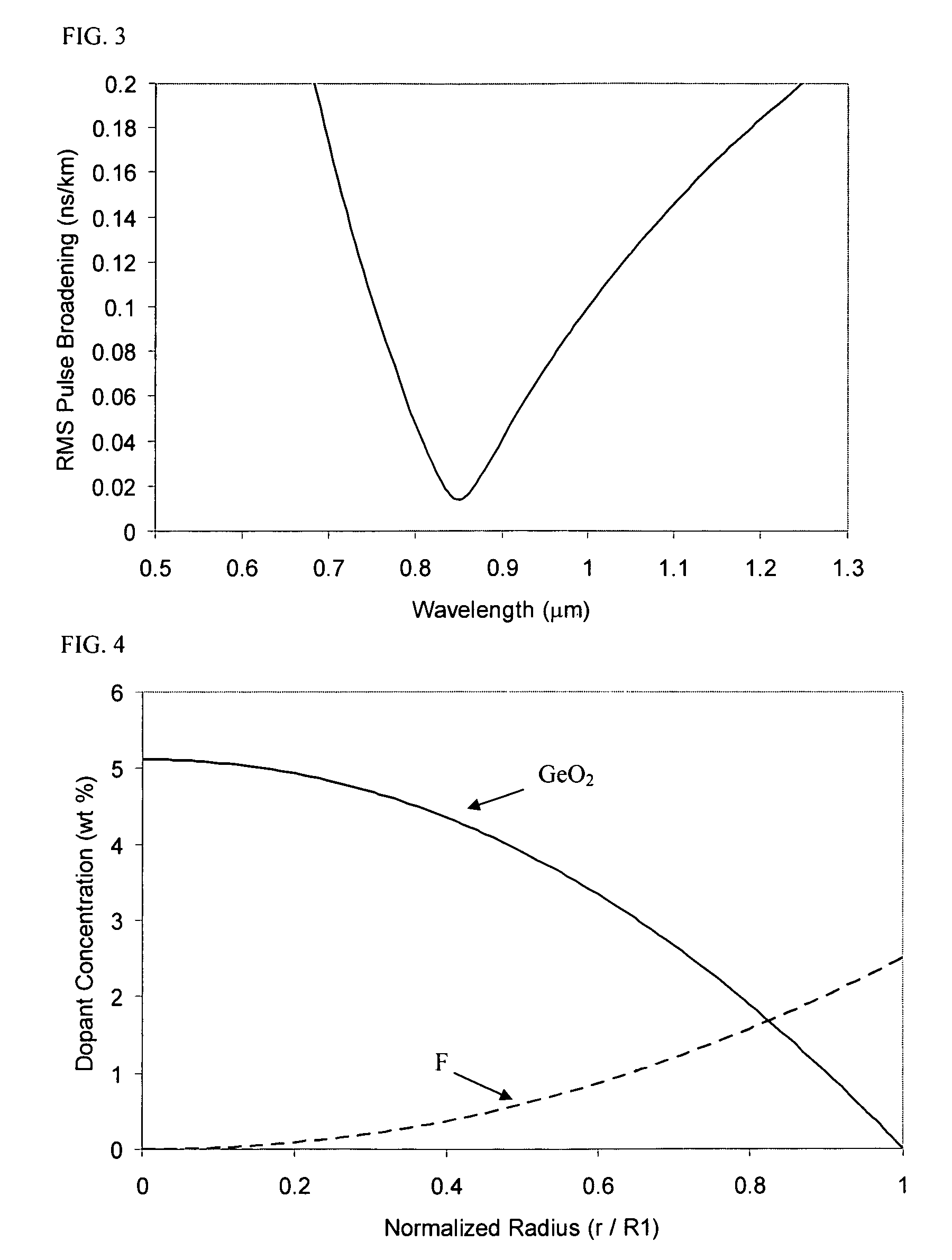
[0042]FIG. 2 schematically depicts the germania dopant concentration profile in the core of a multimode fiber with a graded index refractive index profile intended for operation at 0.85 μm. FIG. 3 shows the root mean square (RMS) pulse broadening as a function of wavelength for the fiber of FIG. 2. The pulse width reaches a minimum at the wavelength of 0.85 μm. For wavelengths away from 0.85 μm, the pulse width increases very rapidly, i.e. the bandwidth decreases. The RMS pulse broadening is less than 0.02 ns / km for all wavelengths between about 0.84 μm and about 0.86 μm, i.e. over a wavelength window width of about 0.02 μm, and over a wavelength window width of 0.02 μm centered at 0.85 μm.

example 2

[0043]FIG. 4 schematically depicts the germania and fluorine dopant concentration profiles, shown as “GeO2” and “F”, respectively, for a multimode optical fiber exemplary of the fibers disclosed herein. Here, α1=α2=2.0708, C11=5.1 wt % germania, C22 =2.5 wt % fluorine, C12=0, C21=0, x1=0.5, x2=0.5, and R1=25 μm. FIG. 5 schematically illustrates the RMS pulse width of the fiber of FIG. 4 at various wavelengths. The RMS pulse broadening is less than 0.02 ns / km for all wavelengths between about 0.75 μm and about 1.0 μm, i.e. over a wavelength window width of about 0.25 μm, and over a wavelength window width of at least 0.20 μm centered at 0.85 μm. Thus, the bandwidth of Example 2 is about 5 times as large as the bandwidth of comparative Example 1.

example 3

Comparative

[0044]FIG. 6 schematically illustrates the RMS pulse width at various wavelengths of a comparative fiber having only germania and no fluorine in the core, shown as curve 3. Here, α1=α2=2.0649 C11=16.2 wt % germania and C22=0 wt % fluorine, C12=0, C21, =0, x1=0.5, x2=0.5, and R1=25 μm. The RMS pulse broadening is less than 0.02 ns / km for all wavelengths between about 0.84 μm and about 0.86 μm, i.e. over a wavelength window width of about 0.02 μm, and over a wavelength window width of 0.02 μm centered at 0.85 μm.


PUM


Abstract

Multimode optical fiber is disclosed herein comprising germania and fluorine co-doped in the core of the fiber. The dopant concentration profiles are defined by a pair of alpha parameters. The operating window, or bandwidth window, is enlarged and attenuation, or loss, is low. In some embodiments, two operating windows are available for transmission.

Description

BACKGROUND OF THE INVENTION[0001]1. Field of the Invention[0002]The present invention relates generally to optical fiber, and particularly to graded index multimode fibers.[0003]2. Technical Background[0004]The bandwidth of multimode fibers (MMF) is limited mostly by inter-modal chromatic dispersion. To minimize the inter-modal chromatic dispersion, MMF are designed with graded index α-profiles. For optimum bandwidth, the parameter α is about 2. However the optimized α value depends on wavelength due to the material dispersion. Because the bandwidth is very sensitive to profile change from its optimum shape, the operating window with high bandwidth is very narrow.[0005]The bandwidth can be increased with multiple dopants. Known fibers utilize co-doping of germanium and boron. However, boron increases fiber attenuation, increasing the transmission losses of the MMF. Other known multimode fibers have at least one dopant which has lower concentration in the fiber axis than concentratio...

Claims


Application Information

Patent Timeline
IPC IPC(8): G02B6/02
CPCG02B6/0288
Inventor LI, MING-JUNNOLAN, DANIEL ALOYSIUSTANDON, PUSHKAR
Owner CORNING INC
Learn More