Lead insertion tool for hemostatic introducer system

Inactive Publication Date: 2008-01-08
CARDIAC PACEMAKERS INC
View PDF2 Cites 56 Cited by
  • Summary
  • Abstract
  • Description
  • Claims
  • Application Information

AI Technical Summary

Benefits of technology

[0010]The present invention comprises a lead insertion tool adapted for use with a lead introducer having an elastomeric hemostasis valve with a self-closing aperture. The tool comprises a tubular sheath having a relatively thin wall with at least one longitudinal groove formed inwardly thereof to facilitate rupture of the sheath along the groove. The lumen of the tubular sheath is sized to receive a medical lead therethrough with a predetermined clearance fit. A tool dilator that has a generally rigid shaft is insertable through the lumen of the tubular sheath and when so inserted renders the sheath sufficiently rigid to allow insertion of the

Problems solved by technology

While introducers of the type described can be used with a variety of pacemaker/defibrillator leads, there are certain lead designs that can be damaged as the distal end portion bearing the electrodes is forced through the self-closing aperture of the hemostatic valve.
As a lead of this type is forced through the hemostasis valve of an introducer, the excessive frictional forces tend to displace the turns of the coil so that they are no longer appropriately spaced.
However, it is found that the SafeSheath introducer incorporates a silicon oil as a lubricant on its hemostasis valve me

Method used


Image

  • Lead insertion tool for hemostatic introducer system
  • Lead insertion tool for hemostatic introducer system
  • Lead insertion tool for hemostatic introducer system

Examples


Embodiment Construction

[0017]Certain terminology will be used in the following description for convenience in reference only and will not be limiting. The words “upwardly”, “downwardly”, “rightwardly” and “leftwardly” will refer to directions in the drawings to which reference is made. The words “inwardly” and “outwardly” will refer to directions toward and away from, respectively, the geometric center of the device and associated parts thereof. Said terminology will include the words above specifically mentioned, derivatives thereof and words of similar import.

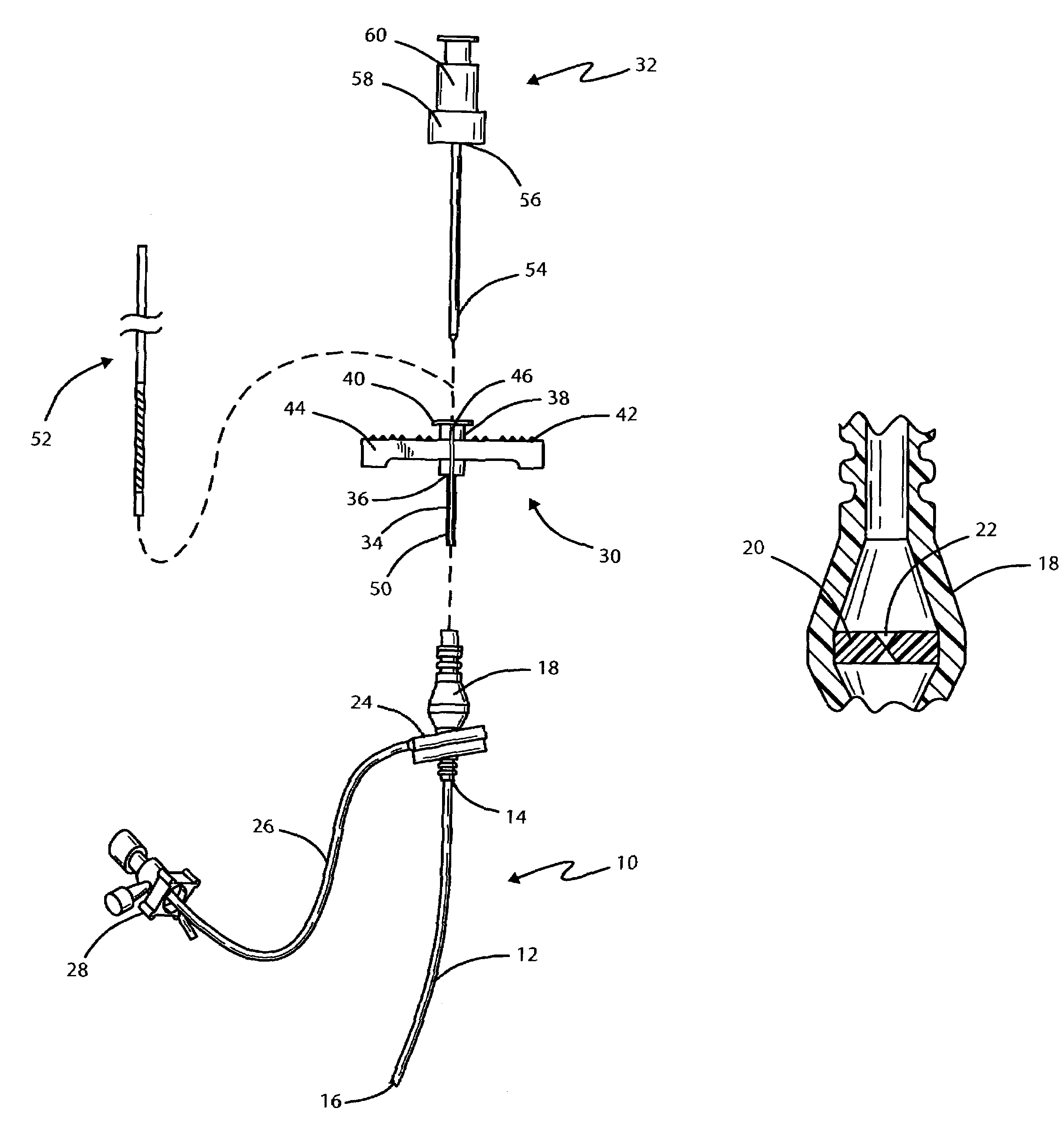
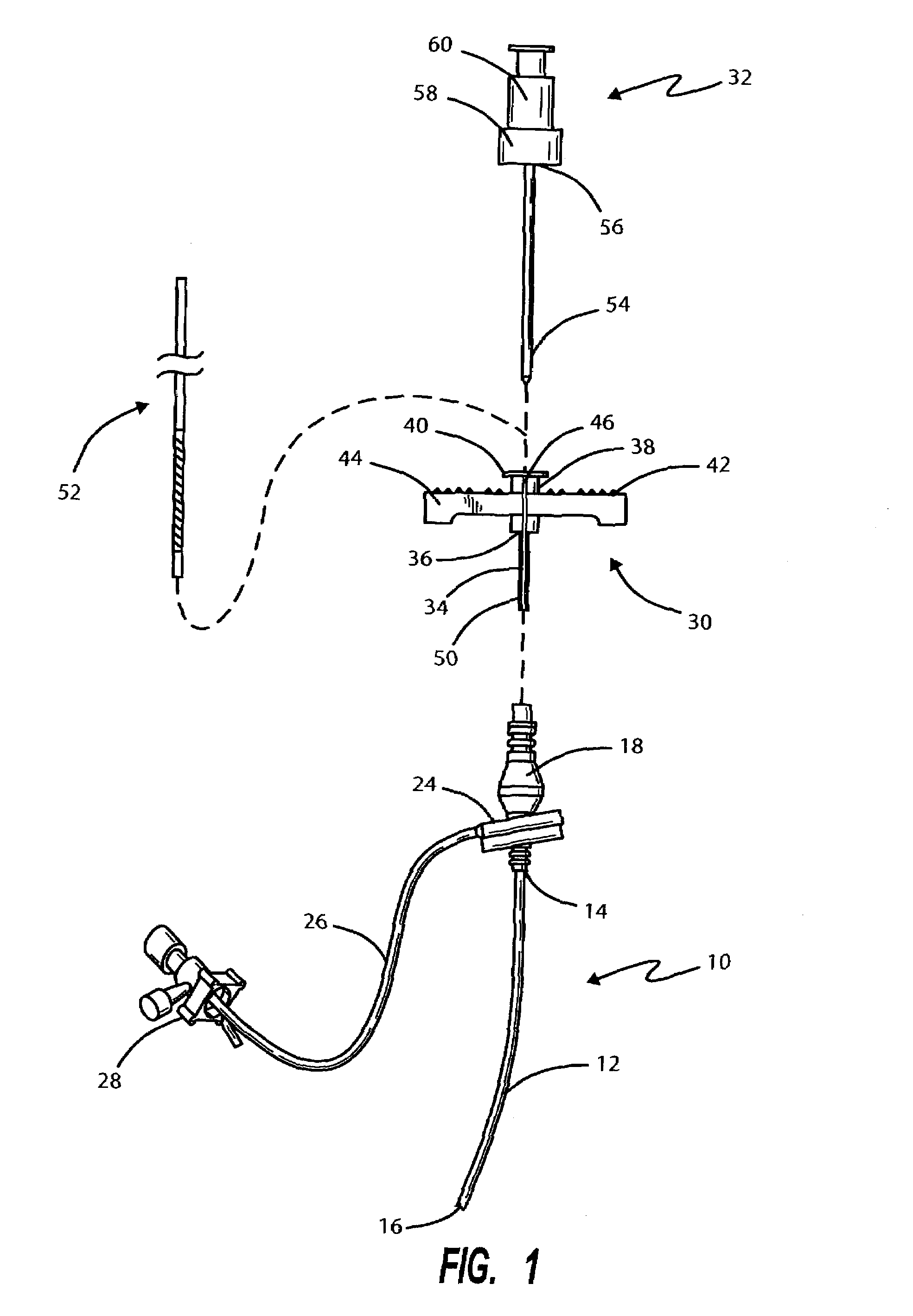
[0018]Referring initially to FIG. 1, there is indicated generally by numeral 10 a conventional introducer set of a type used in implanting medical leads for an implantable pacemaker or pacemaker defibrillator. It is seen to comprise a flexible, tubular sheath 12 having a proximal end 14 and a distal end 16 and with a lumen extending therebetween. Completing the set is a dilator (not shown). Affixed to the proximal end 14 of the sheath 12 is a hub m...


PUM


Abstract

A tool for protecting a cardiac stimulating lead from damage upon passing through a hemostasis valve of a vascular introducer in the course of an implantation procedure comprises a splittable, peal-away sheath that is rendered sufficiently rigid by a tool dilator or placement of the lead body within the sheath so that the combination can be forced through a self-closing aperture formed through the hemostatic valve member. The use of the tubular sheath in breaching the self-closing aperture shields the lead electrodes and any covering that may be present from becoming distorted as well as from contamination by silicon oil commonly found in vascular introducers having a hemostasis valve.

Description

BACKGROUND OF THE INVENTION[0001]I. Field of the Invention[0002]This invention relates generally to implantable tissue stimulating apparatus of the type having a pulse generator and a medical lead for delivering electrical stimulation to target tissue, and more particularly to a tool to be used in facilitating the surgical implantation of a medical lead into a patient's body.[0003]II. Discussion of the Prior Art[0004]In implanting medical devices, such as pacemakers or pacemakers / defibrillators, a transvenous lead placement approach has found wide acceptance. Using the Seldinger technique, the right or left cephalic vein or the axillary vein is located and punctured with a relatively long, large-bore needle. A guidewire is then typically passed through the needle into the selected vein. The needle is then removed from the guidewire and replaced with an introducer incorporating a hemostasis valve to stem blood flow. Once the introducer is in place, the medical lead is forced through ...

Claims


Application Information

Patent Timeline
IPC IPC(8): A61M5/178A61B17/34A61N1/05
CPCA61B17/3468A61N1/05A61N1/056A61B17/3462A61B17/3498
Inventor LINDSTROM, CURTIS C.KADERA, JAMES D.
Owner CARDIAC PACEMAKERS INC
Why Eureka
Try Eureka