Power output apparatus and motor vehicle equipped with power output apparatus

a technology of power output apparatus and motor vehicle, which is applied in the direction of electric generator control, jet propulsion mounting, electric devices, etc., can solve the problems of low degree of freedom in the operation of the two engines, and the engine in the other structure configuration is not allowed to drive, so as to improve the overall energy efficiency of the whole motor vehicle and achieve high degree of freedom of operation.

Inactive Publication Date: 2008-01-08
TOYOTA JIDOSHA KK
View PDF12 Cites 42 Cited by
  • Summary
  • Abstract
  • Description
  • Claims
  • Application Information

AI Technical Summary

Benefits of technology

[0006]The invention regards a power output apparatus with two motors and two internal combustion engines, as well as a motor vehicle equipped with the power output apparatus. The object of the invention is to provide a structure of the power output apparatus or the motor vehicle that attains a high degree of freedom in operations of the two internal combustion engines. The object of the invention is also to enhance the overall energy efficiency of the whole power output apparatus or the whole motor vehicle.
[0009]The power output apparatus of the invention has the multi-axes-type power input output mechanism, which has the multiple axes including the four axes, that is, the first axis linked to the output shaft of the first internal combustion engine, the second axis linked to the output shaft of the second internal combustion engine, the third axis linked to the rotating shaft of the first motor, and the fourth axis linked to the rotating shaft of the second motor. The driveshaft is connected with one of these four axes, and the two axes of the four axes are rotated based on the rotation speeds of the remaining two axes. The multi-axes-type power input output mechanism works to output the power to the driveshaft with balance of at least the input and output powers between these four axes and the first internal combustion engine, the second internal combustion engine, the first motor, and the second motor. Appropriate operation controls of the first internal combustion engine, the second internal combustion engine, the first motor, and the second motor desirably enhance the overall energy efficiency of the whole power output apparatus.
[0011]In one preferable embodiment of the power output apparatus of the invention, the multi-axes-type power input output mechanism includes a first connection-disconnection mechanism that connects and disconnects the first axis with and from the output shaft of the first internal combustion engine, and a second connection-disconnection mechanism that connects and disconnects the second axis with and from the output shaft of the second internal combustion engine. In the power output apparatus of this embodiment, adequate controls of the first connection-disconnection mechanism and the second connection-disconnection mechanism desirably increase the degree of freedom in operations of the first internal combustion engine and the second internal combustion engine. The first internal combustion engine and the second internal combustion engine may be driven at efficient drive points or may stop their operations to ensure the enhanced overall energy efficiency of the whole power output apparatus. In the power output apparatus of this preferable embodiment, at least one of the first connection-disconnection mechanism and the second connection-disconnection mechanism may be a one-way clutch. The first connection-disconnection mechanism and the second connection-disconnection mechanism then readily attain the connection or the disconnection by simple operation of the relevant internal combustion engine.
[0013]In one preferable embodiment of the invention, the power output apparatus further includes: a power demand setting module that sets a power demand required for the driveshaft, in response to an operator's operation; and a control module that controls the first internal combustion engine, the second internal combustion engine, the first motor, the second motor, and the multi-axes-type power input output mechanism to output a power equivalent to the set power demand to the driveshaft. This arrangement ensures output of the required power to the driveshaft in response to the operator's operation. The control module may control the first internal combustion engine, the second internal combustion engine, the first motor, the second motor, and the multi-axes-type power input output mechanism to ensure efficient output of the power equivalent to the set power demand to the driveshaft. This arrangement desirably enhances the overall energy efficiency of the whole power output apparatus.
[0015]In another preferable embodiment of the power output apparatus of the invention, the multi-axes-type power input output mechanism includes a first planetary gear unit having three rotational elements and a second planetary gear unit having three rotational elements, where any two rotational elements of the three rotational elements in the second planetary gear unit are respectively connected with any two rotational elements of the three rotational elements in the first planetary gear unit. The four axes of the multi-axes-type power input output mechanism include one axis connected to a remaining rotational element of the three rotational elements of the second planetary gear unit, which is not connected with any of the three rotational elements of the first planetary gear unit, and three axes connected to the three rotational elements of the first planetary gear unit. The multi-axes-type power input output mechanism is readily constructed by combination of two planetary gear units.
[0017]The motor vehicle of the invention is equipped with the power output apparatus having any of the above applications or structures, and accordingly has the similar effects and functions to those of the power output apparatus of the invention described above. Appropriate operation controls of the first internal combustion engine, the second internal combustion engine, the first motor, and the second motor desirably enhance the overall energy efficiency of the whole motor vehicle. The motor vehicle of the invention has the high degree of freedom in operations of the first internal combustion engine and the second internal combustion engine.

Problems solved by technology

Namely the engine in the other structure configuration is not allowed to be driven at an efficient drive point.
In this prior art power output apparatus, there is only a low degree of freedom in operations of the two engines.
One of the primary issues with regard to such power output apparatuses is enhancement of energy efficiency.

Method used


Image

  • Power output apparatus and motor vehicle equipped with power output apparatus
  • Power output apparatus and motor vehicle equipped with power output apparatus
  • Power output apparatus and motor vehicle equipped with power output apparatus

Examples


first embodiment

A. First Embodiment

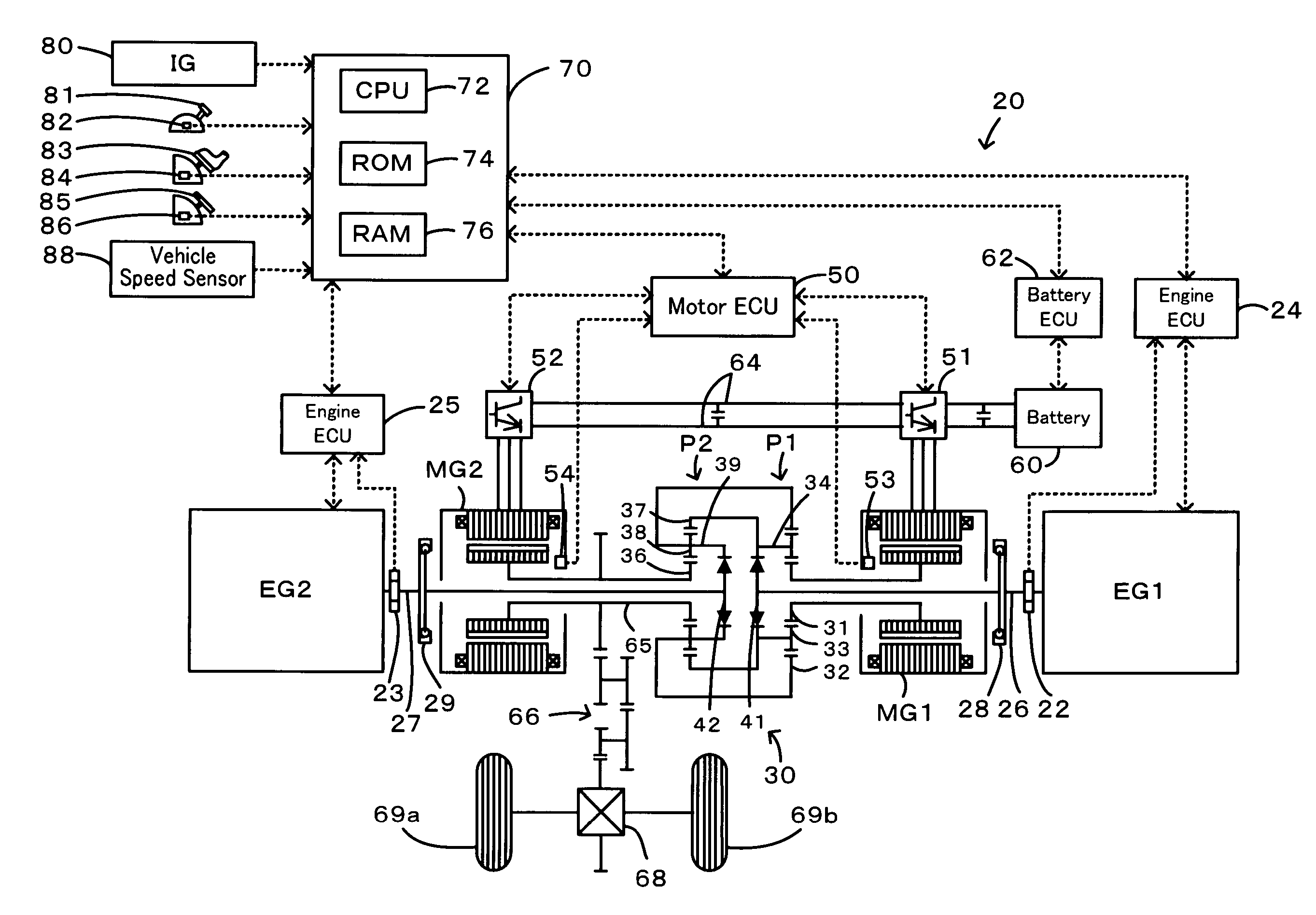
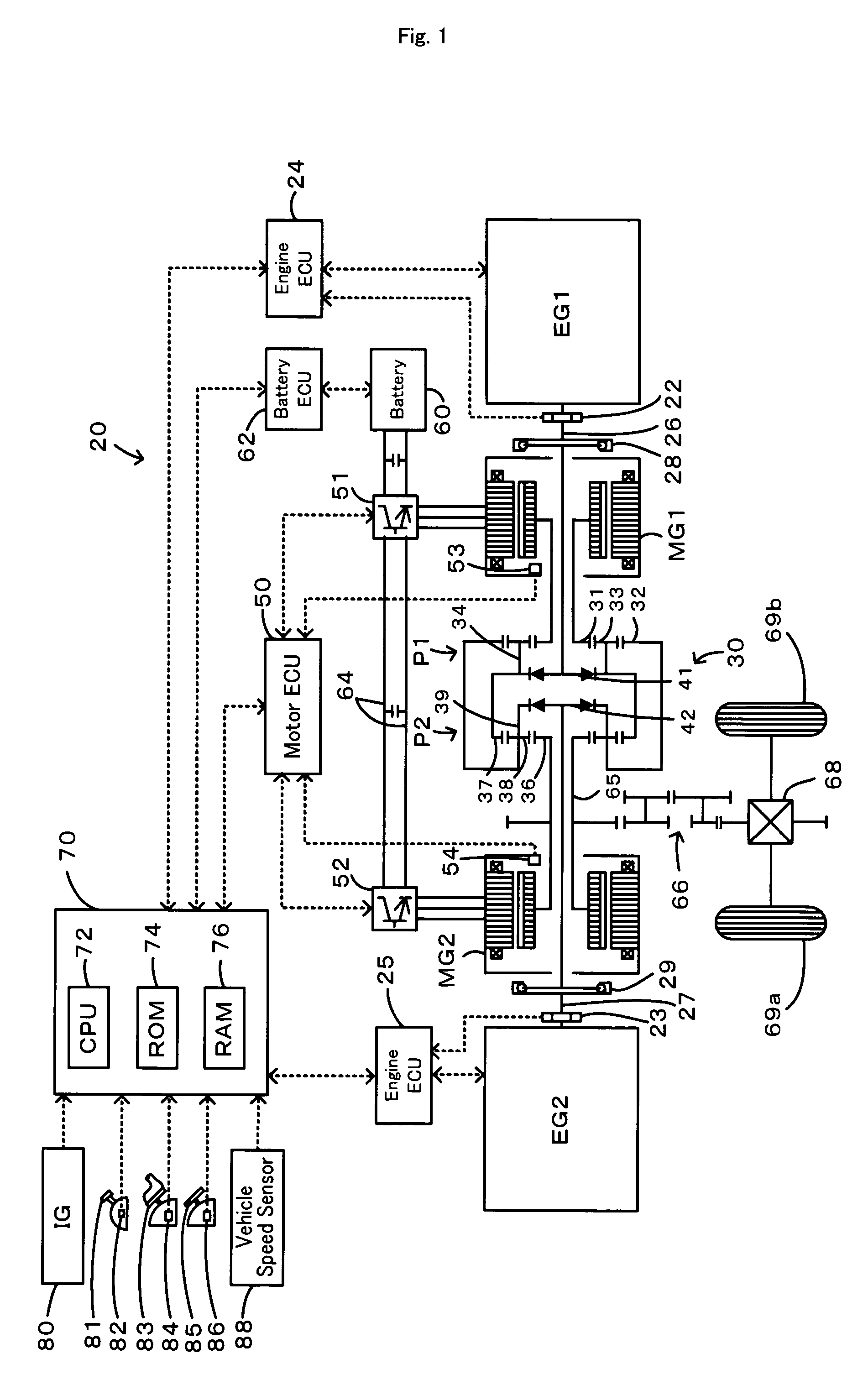
[0039]FIG. 1 schematically illustrates the configuration of a hybrid vehicle 20 equipped with a power output apparatus in a first embodiment of the invention. As illustrated, the hybrid vehicle 20 of the first embodiment includes two engines EG1 and EG2, a four axes-type power distribution integration mechanism 30 that is connected to crankshafts 26 and 27 of the engines EG1 and EG2 via dampers 28 and 29 and is also connected to drive wheels 69a and 69b via a differential gear 68 and a gear mechanism 66, a motor MG1 that is linked with the power distribution integration mechanism 30 and has power generation capability, a motor MG2 that is also linked with the power distribution integration mechanism 30 and has power generation capability, and a hybrid electronic control unit 70 that controls the operations of the whole power output apparatus. The engines EG1 and EG2 are both internal combustion engines that consume a hydrocarbon fuel, such as gasoline or light oil...

second embodiment

B. Second Embodiment

[0065]FIG. 13 schematically illustrates the configuration of another hybrid vehicle 120 equipped with a power output apparatus in a second embodiment of the invention. The hybrid vehicle 120 of the second embodiment has the same configuration as that of the hybrid vehicle 20 of the first embodiment, except the structure of a power distribution integration mechanism 130. The like elements included in the hybrid vehicle 120 of the second embodiment to those of the hybrid vehicle 20 of the first embodiment are thus expressed by the like numerals and symbols and are not specifically described here.

[0066]As shown in FIG. 13, the power distribution integration mechanism 130 mounted on the hybrid vehicle 120 of the second embodiment includes two single pinion planetary gears P3 and P4, a clutch C1, and a one-way clutch 141. A sun gear 131, a ring gear 132, and a carrier 134 linked with a pinion gear 133 of the third planetary gear P3 are respectively connected to the ro...


PUM


Abstract

A motor (MG1) is connected to a sun gear (31) of a first planetary gear (P1) of a power distribution / unification mechanism (30), an engine (EG1) is connected to a carrier (34) of the first planetary gear (P1) and a ring gear (37) of a second planetary gear (P2), an engine (EG2) is connected to a ring gear (32) of the first planetary gear (P1) and a carrier (39) of the second planetary gear (P2), and a motor (MG2) and a drive shaft (65) are connected to a sun gear (36) of the second planetary gear (P2). Drive control is made by selecting an operation pattern from the following operation patterns, the operation pattern to be selected is the pattern enabling efficient operation according to a demand by an operator: a first operation pattern where power is outputted from the engine (EG2) to the drive shaft (65), a second operation pattern where power is outputted from the engine (EG1) to the drive shaft (65), a third operation pattern where power is outputted from both engines (EG1, EG2) to the drive shaft (65), and a motor operation mode where the engines (EG1, EG2) are stopped and power is outputted from the motor (MG2) to the drive shaft (65).

Description

[0001]This is a 371 national phase application of PCT / JP2005 / 003241 filed 21 Feb. 2005, claiming priority to Japanese Patent Application No. 2004-107274 filed 31 Mar. 2004. the contents of which are incorporated herein by reference.TECHNICAL FIELD[0002]The present invention relates to a power output apparatus and a motor vehicle equipped with the power output apparatus. More specifically the invention pertains to a power output apparatus that outputs power to a driveshaft, as well as a motor vehicle that is equipped with the power output apparatus.BACKGROUND ART[0003]One proposed power output apparatus mounted on a motor vehicle has two structure configurations, in each of which an engine is connected to a rotating shaft of a motor via a clutch. In this prior art power output apparatus, an actuator unit is attached to a transmission linked with an axle of the motor vehicle, and the two structure configurations are connected to the actuator unit via respective clutches and brakes (se...

Claims


Application Information

Patent Timeline
Patent Type & Authority Patents(United States)
IPC IPC(8): B60L11/14B60W20/00B60K5/08B60K6/445B60K17/04B60L50/16B60W10/02B60W10/06B60W10/08F02B73/00
CPCB60K5/08B60K6/365B60K6/445B60W10/02B60W10/06B60W10/08B60W20/00F02B73/00B60W2540/10F16H3/728F16H2037/0866F16H2200/2007Y02T10/6286Y02T10/6239B60L15/2045B60L15/2054B60L2220/42B60L2240/12B60L2240/14B60L2240/421B60L2240/423B60L2240/441B60L2240/443B60L2240/507B60L2250/28Y02T10/72B60L50/16Y02T10/62Y02T10/64Y02T10/7072B60W20/10Y02T10/70
Inventor YAMAUCHI, TOMOKAZU
Owner TOYOTA JIDOSHA KK
Why Eureka
Try Eureka