
Precious metal recovery

Inactive Publication Date: 2008-01-15
HESSABI IRADJ
View PDF9 Cites 13 Cited by
  • Summary
  • Abstract
  • Description
  • Claims
  • Application Information

AI Technical Summary

Benefits of technology

[0006]According to one aspect of the present invention, a mineral deposit has one or more types of metals embedded therein. While the deposit is under water, an electric pulse of o

Problems solved by technology

Black sand cannot be refined through either the chemical, high temperature or grinding process.
From the description given hereinbefore, a conventional refining of gold ore that involves a use of caustic chemicals, is undesirably time consuming and is expensive.
Additionally, there may be an undesired chemical alteration of some of the matter comprising the ore.

Method used


Image

  • Precious metal recovery
  • Precious metal recovery
  • Precious metal recovery

Examples


Embodiment Construction

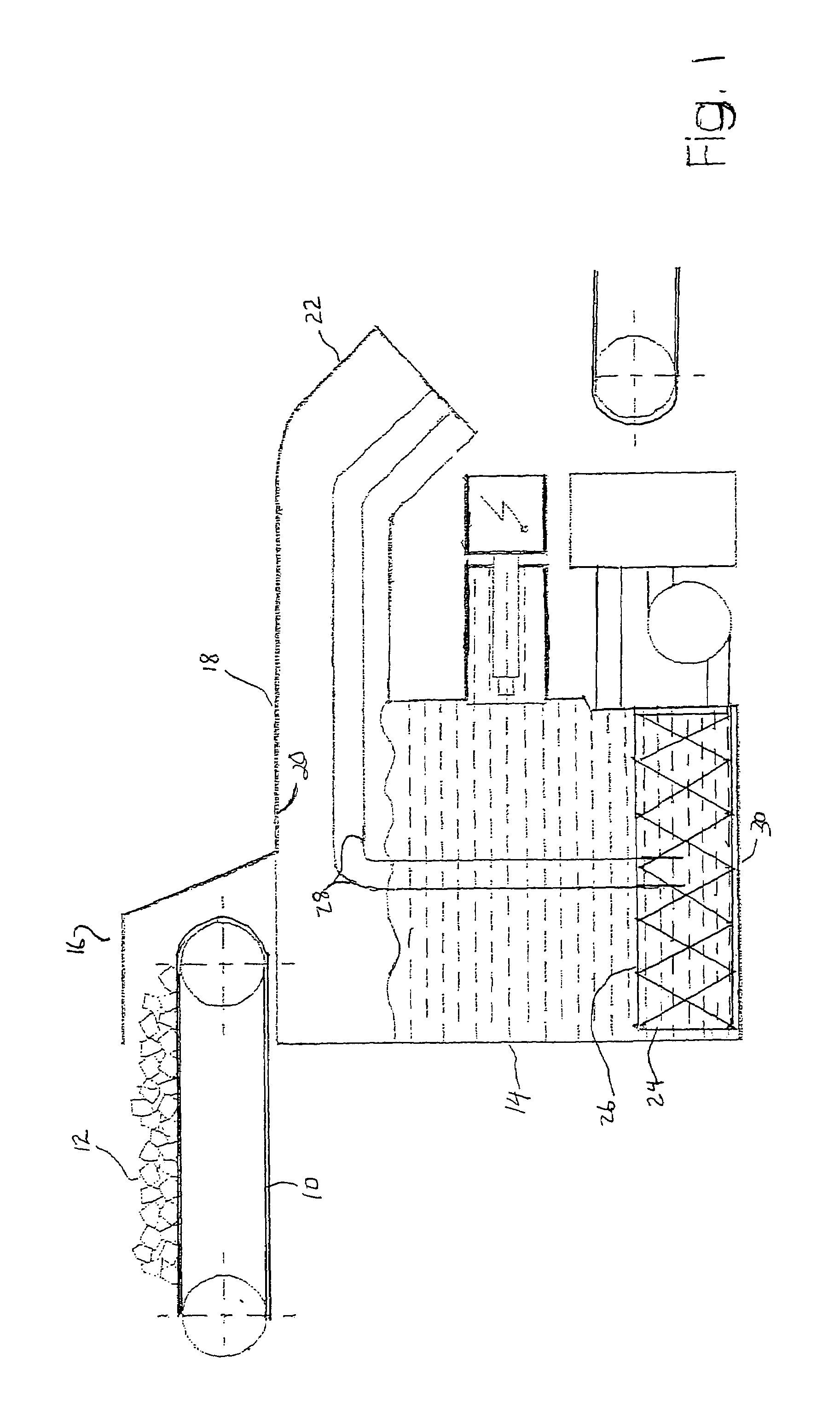
[0015]A first object of a recovery process described herein is to separate metals from rock wherein the metals are embedded. As shown in FIG. 1, a conveyor 10 carries silicon rocks 12 with the metals embedded therein. The conveyor 10 is proximal to a water filled tank 14 at an entrance port 16 thereof. The conveyer 10 is operable to transport rocks from a storage location to the port 16.

[0016]An upper portion of the tank 14 includes a chute 18. Although the chute 18 is generally horizontal, it has an end slopes downward to provide an exit port 22 from the tank 14.

[0017]Within the tank 14 is a crib 24 of wire mesh construction. The crib 24 has an open top 26. Additionally, tracks 28 extend from a location near a bottom 30 of the tank 14, through the entrance port 20 to the exit port 22. The crib 24 is moveable along the tracks 28.

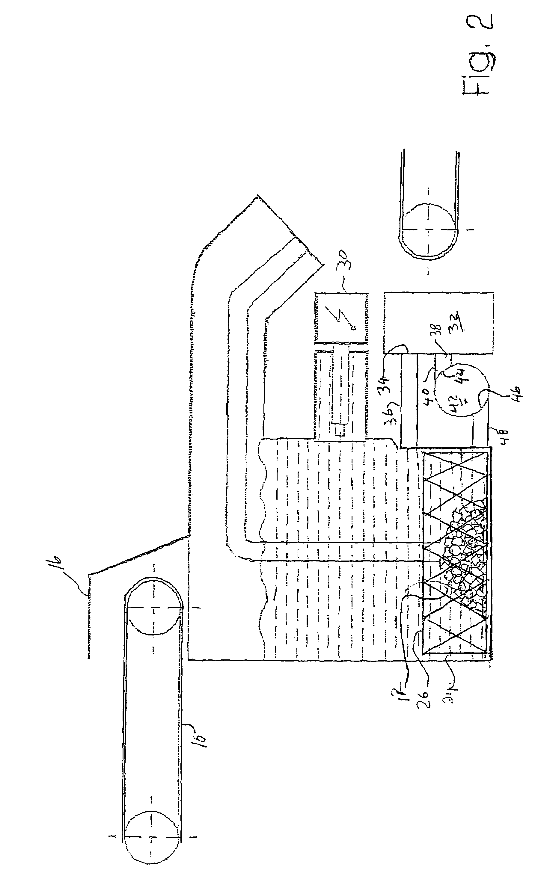
[0018]As shown in FIG. 2. the rocks 12 are dumped from the conveyor 10 through the top 26 into the crib 24. Thereafter, a generator 30 generates a pulse of ...


PUM


Abstract

A pulse of over six kilovolts with a duration of 200 nanoseconds causes an explosion that fragments a mineral deposit with metals embedded therein. The fragmentation separates the metals from the mineral. A conditioning electromagnet temporarily magnetizes the metals. A sorting magnet attracts one of the magnetized metals.

Description

FIELD OF INVENTION[0001]This invention is in the field of precious metal recovery and, more particularly, causing an electrically generated explosive fragmentation that separates the metals from waste materials.DESCRIPTION OF THE PRIOR ART[0002]Present day extraction of precious metals from ore is done mainly with chemicals, high temperature furnaces or grinding machines. In a chemical extraction process, for example, a cyanide mixture is prepared from sodium cyanide crystals that are dissolved in a small volume of water and boiled with sodium peroxide. The cyanide mixture is usually placed in a tank with water wherein calcium oxide is added to form a solution that is alkaline. The gold ore is placed within the solution.[0003]The recovery of the gold is accomplished by circulating the solution through charcoal filters that are then washed with hot alkalies, such as sodium hydroxide, that augment the solution. Zinc is used to reduce the gold from the augmented solution.[0004]There is...

Claims


Application Information

Patent Timeline
IPC IPC(8): B03C1/00
CPCB03C1/002B03C1/0335B03C1/22
Inventor HESSABI, IRADJ
Owner HESSABI IRADJ
Learn More