Method and apparatus for controlling magnetostriction in a spin valve sensor

a technology of spin valve sensor and magnetostriction, which is applied in the field of magnetic recording technology, can solve the problems of adverse magnetic strain on the stability of the read head

Inactive Publication Date: 2008-01-15
WESTERN DIGITAL TECH INC
View PDF14 Cites 146 Cited by
  • Summary
  • Abstract
  • Description
  • Claims
  • Application Information

AI Technical Summary

Benefits of technology

[0009]FIG. 1 is a diagram of a conventional magnetic element.
[0010]FIG. 2 is a flow chart depicting a conventional method for fabricating a conventional magnetic element.
[0011]FIG. 3 is a high level diagram of a conventional system for fabricating a conventional magnetic element.

Problems solved by technology

A high magnetostriction adversely affect the stability of a read head (not shown) incorporating the conventional magnetic element 10.

Method used


Image

  • Method and apparatus for controlling magnetostriction in a spin valve sensor
  • Method and apparatus for controlling magnetostriction in a spin valve sensor
  • Method and apparatus for controlling magnetostriction in a spin valve sensor

Examples


Embodiment Construction

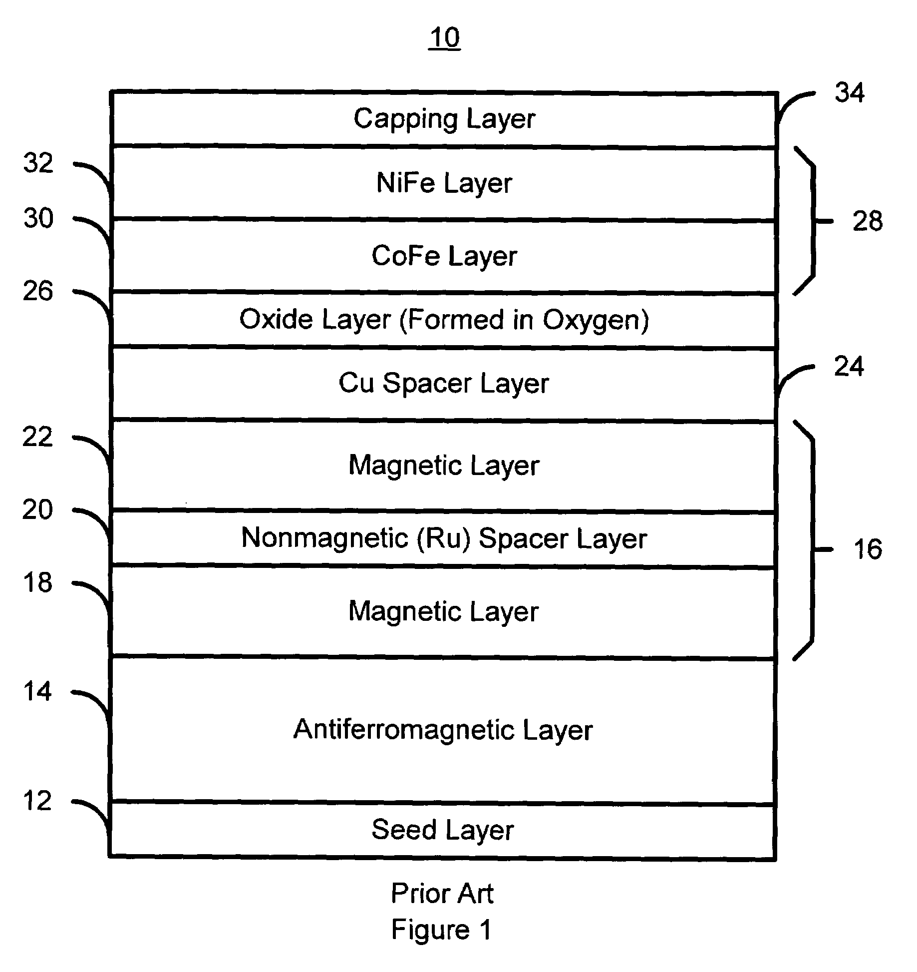
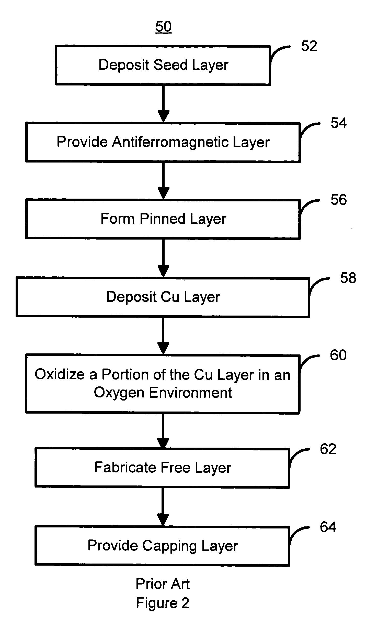
[0020]FIG. 4 depicts a diagram of a magnetic element 100 in accordance with one enabling and exemplary embodiment of the present invention. The magnetic element includes at least a pinned layer 106, a spacer layer 114, an oxide layer 116, and a free layer 118. The pinned layer 106 is preferably a synthetic pinned layer including ferromagnetic layers 108 and 112 separated by a conductive, nonmagnetic spacer layer 110. The nonmagnetic spacer layer 110 is preferably composed of Ru and has a thickness that is configured such that the magnetizations of the ferromagnetic layers 108 and 112 are antiferromagnetically aligned. The free layer 118 is preferably a bilayer including a CoFe layer 120 and a NiFe layer 122. The spacer layer 114 is a conductor, is nonmagnetic, and preferably comprised of Cu. The oxide layer 116 is an oxide of the same conductor used in forming the spacer layer 114. Furthermore, the oxide layer 116 is formed as described below, by oxidizing a portion of the conductor...


PUM

PropertyMeasurementUnit
diameteraaaaaaaaaa
diameteraaaaaaaaaa
magnetoresistiveaaaaaaaaaa

Abstract

A method and system for providing a magnetic element are described. The method and system include providing a pinned layer, fabricating a metallic spacer layer and oxidizing a portion of the spacer layer in an environment including at least oxygen and a gas inert with respect to the spacer layer to provide an oxide layer. The method and system also include creating a free layer. The oxide layer is between a remaining metallic portion of the spacer layer and the free layer. In one aspect, the system includes a chamber and a gas diffusion apparatus within the chamber. The gas diffusion apparatus includes a plurality of nozzles and defines a plane. The gas exits each of the plurality of nozzles in a cone having an apex angle. The nozzles are directed at a nozzle tilt angle of at least half of the apex angle from the plane and the spacer layer.

Description

FIELD OF THE INVENTION[0001]The present invention relates to magnetic recording technology, and more particularly to a method and system for providing a spin valve sensor that has improved magnetostriction.BACKGROUND OF THE INVENTION[0002]FIG. 1 depicts a conventional magnetic element 10, typically termed a spin valve, that exhibits giant magnetoresistance. The conventional magnetic element 10 includes a seed layer 12, an antiferromagnetic (AFM) layer 14, a pinned layer 16, a conventional spacer layer 24, a conventional oxide layer 26, a pinned layer 28, and a capping layer 34. The pinned layer 16 is a synthetic pinned layer including two ferromagnetic layers 18 and 22 separated by a nonmagnetic conductive spacer layer 20 that is typically Ru. The conventional oxide layer 26 is an oxide of Cu, formed as described below. The conventional free layer 28 includes a bilayer having a CoFe layer 30 and a NiFe layer 32.[0003]FIG. 2 depicts a conventional method 50 for providing the conventi...

Claims


Application Information

Patent Timeline
Patent Type & Authority Patents(United States)
IPC IPC(8): B05D5/12
CPCB82Y25/00B82Y40/00G01R33/09G01R33/18H01F10/3272H01F41/305H01L43/12H01F10/3259G11B5/3906Y10T29/49067H10N50/01
Inventor PARK, CHANG-MANFUNADA, SHINRANA, AMRITPAL S.SCOTT, DANIEL E.
Owner WESTERN DIGITAL TECH INC
Why Eureka
Try Eureka