
Apparatus and methods for reduction of coherent noise in a digital signal averager

a digital signal averager and coherent noise technology, applied in the field of repetitive electronic waveform measurement, can solve the problems of inability to meet the corresponding memory requirements, and uncertainty in the relative phases of different recordings of the waveform, so as to achieve the effect of reducing coherent noise and random noise reduction

Inactive Publication Date: 2008-01-22
PERKINELMER HEALTH SCIENCES INC
View PDF4 Cites 25 Cited by
  • Summary
  • Abstract
  • Description
  • Claims
  • Application Information

AI Technical Summary

Benefits of technology

[0024]A digital signal averager (DSA) for digitizing and digital signal averaging a repetitive analog waveform is provided. Specifically, a DSA is provided that includes devices and methods which enable signal averaging to be accomplished while reducing internally-generated coherent noise without suffering any of the disadvantages associated with the prior art. Fundamentally, the apparatus and methods of the present invention provides means to introduce a known phase offset between a signal waveform being measured, and the repetitive pattern of internally generated digital voltage transitions that give rise to coherent noise in a signal waveform measured with a DSA. The known phase offset is different for different scans of the repeated waveform, such that the signal at any particular point in the waveform is digitized in each scan during a different phase of the cycle of digital data transfer, processing, and storage associated with the signal-averaging sequence. The known phase offset of each scan is properly accounted for during the summation, or signal-averaging, process, so that each scan maintains coherency with all other measured signal waveforms during the summation process. Hence, each point in the signal waveform will be sampled during each scan with a different value, that is, during a different phase, of the repetitive coherent noise background; hence, the coherent noise will be, essentially, averaged as a result of this process. Consequently, the coherent noise in the signal-averaged waveform is reduced by averaging according to apparatus and methods of the present invention, thereby improving the signal-to-noise ratio and signal dynamic range of such measurements more effectively than with previous methods.
[0034]The signal averaging process, as described above according to the embodiments and methods of operation of the present invention, will produce the same reduction in random noise as is realized with conventional signal averaging (assuming that the same number of scans are signal averaged as with conventional signal averaging). However, in contrast to conventional DSA's, the apparatus and methods of the present invention uniquely provide means to reduce coherent noise, which originates from within the DSA, as well as random noise.

Problems solved by technology

However, a large number of records is usually desired for signal averaging in practice, and the corresponding memory requirements usually, but not always, become impractical with such an approach.
In such situations, there will inevitably be an uncertainty in the relative phases between different recordings of the waveform of up to plus or minus one ADC digitization interval because of the lack of synchronization between the signal waveform and the ADC clock internal to the DSA.
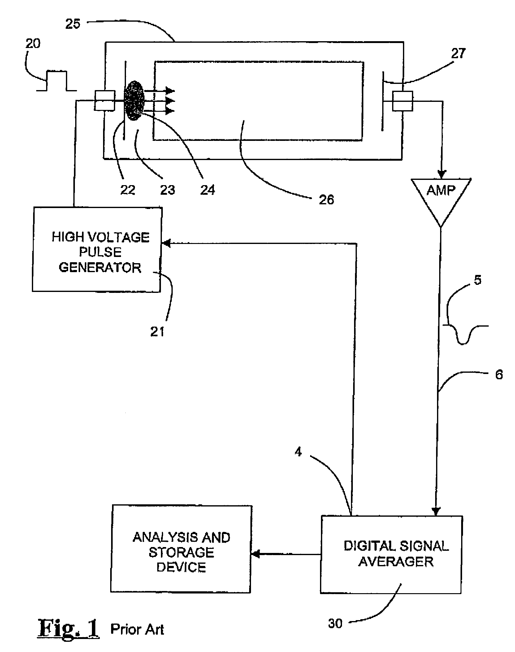
However, coherent noise may also originate from within the digital signal averager itself, often due, for example, to coupling between the signal input and voltage transitions that occur internal to the DSA.
Because the sequence of such voltage transitions are repeated precisely for each digitization, the noise that they generate at the signal input is repetitive and synchronous with the signal waveform being averaged.
Therefore, for signal levels in the measured waveforms that are at least as great as the applied constant voltage offset, this approach is unable to reduce the waveform distortions caused by coherent noise.
Such waveform distortions due to coherent noise are especially problematic for relatively small signal levels, which are of amplitudes that are just great enough to correspond to the voltage level of 1, or several, LSB's.
In these cases, the voltage excursions due to the coherent noise result in substantial noise on such small signal levels, which frustrates any attempt to obtain an accurate measurement, and limit the dynamic range of the DSA.
Furthermore, such a voltage offset precludes the measurement of any signal with a magnitude less than that of the voltage offset, and therefore further limits the signal dynamic range capability of the DSA.
Unfortunately, such filtering techniques unavoidably distort all features in the waveform, including the desired signal waveform characteristics, at least to some extent, and such distortion of the desired waveform is often unacceptable.
Unfortunately, this is usually not the case.
Therefore, the subtraction of a background coherent noise spectrum from a signal waveform will only be effective for the portions of the signal waveform that are similar in amplitude, relative to a bit transition, as the zero-offset level with which the background coherent noise spectrum was measured, and therefore, such background subtraction is of limited utility.
Even further, such background coherent noise subtraction may, in fact, result in an actual increase in coherent noise for some other portions of the measured signal spectrum, specifically, with amplitudes that correspond to voltage levels between two bit transitions, and, therefore, which would have appeared to be relatively free of coherent noise without the coherent noise background subtraction.
In summary, there has not been available a satisfactory solution to the reduction of internally-generated coherent noise in repetitive signal waveforms measured with digital signal averagers.
Therefore, the signal-to-noise ratio and signal dynamic range that may be achieved with current state-of-the-art DSA's has been limited.

Method used


Image

  • Apparatus and methods for reduction of coherent noise in a digital signal averager
  • Apparatus and methods for reduction of coherent noise in a digital signal averager
  • Apparatus and methods for reduction of coherent noise in a digital signal averager

Examples


Embodiment Construction

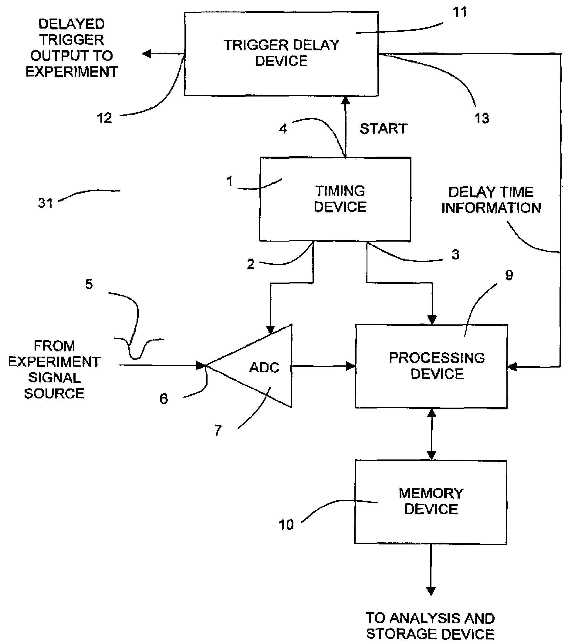
[0072]A digital signal averager configured according to one preferred embodiment of the present invention is shown schematically in FIG. 4A, and consists essentially of an ADC 7, a timing device 1, a processing device 9, a memory device 10, and a trigger delay device 11.

[0073]The timing device 1 includes a precision clock and auxiliary timing circuitry. One function of timing device 1 is to provide a timing signal at output 2 to control the time interval, TBin, between consecutive analog-to-digital conversions by the ADC 7.

[0074]A second function of timing device 1 is to provide a Start signal at output 4 that is synchronized with the ADC digitization cycle. This Start signal is generated at the initiation of a new scan measurement sequence, and is provided to the input of the trigger delay device 11. In response to this Start signal, the trigger delay device 11 produces a trigger signal at output 12, which is routed to the external experiment in order to stimulate a signal response...


PUM


Abstract

Apparatus and methods are provided for reducing coherent noise in measurements of repetitive analog signal waveforms by digital signal averagers. Coherent noise is repetitive and synchronous with the signal waveform and is therefore undiminished by conventional signal averaging techniques. A major source of coherent noise is the repetitive voltage transitions that occur within the digital signal averager itself. The apparatus and methods of the present invention introduce a known and variable phase offset during the signal averaging process between the signal waveform being measured and the internally generated coherent noise, thereby allowing such coherent noise to be averaged, and therefore reduced, during the signal averaging process. Consequently, the apparatus and methods of the present invention allow greater signal-to-noise ratio and signal dynamic range than with the prior art.

Description

RELATED APPLICATIONS[0001]This application is related to patent application Ser. No. 10 / 421,590 filed on Apr. 23, 2003, which was based on Provisional Application No. 60 / 374,943, filed on Apr. 23, 2002.FIELD OF THE INVENTION[0002]The present invention relates to the measurement of repetitive electronic waveforms. More specifically, the present invention provides methods and apparatus for reducing internally generated noise for instruments in which analog-to-digital converters digitize such waveforms and wherein repeated measurements are averaged to improve the signal-to-noise ratio and the dynamic range characteristics of the measurement.BACKGROUND OF THE INVENTION[0003]Various kinds of signal recording technologies are employed in many different kinds of instruments for the measurement of a time-varying voltage, such as x-y recorders, oscilloscopes, and analog-to-digital converters (ADC's) combined with memory arrays. In the latter configuration, the voltage waveform is recorded by...

Claims


Application Information

Patent Timeline
IPC IPC(8): G06F15/00G06F7/38
CPCH01J49/0036
Inventor WELKIE, DAVID G.WHITEHOUSE, CRAIG M.
Owner PERKINELMER HEALTH SCIENCES INC
Learn More