Method and apparatus for curing a fiber having at least two fiber coating curing stages

a technology of curing stage and fiber, which is applied in the direction of lighting and heating apparatus, drying machines, instruments, etc., can solve the problems of not addressing the cure level of the coating, affecting the geometry and performance of the fiber in the optical fiber ribbon and cable structure, and not completely curing the uv curable coating applied to the optical fiber. achieve the effect of optimal coating cur

Inactive Publication Date: 2008-01-29
DRAKA COMTEQ BV
View PDF34 Cites 164 Cited by
  • Summary
  • Abstract
  • Description
  • Claims
  • Application Information

AI Technical Summary

Benefits of technology

[0020]The present invention provides a number of advantages. First, some of the UV cure stages may be eliminated. This adds a cost benefit of not requiring the use of additional UV cure stages and the associated equipment costs. Also, the maintenance cost associated with replacing the various component parts of the UV cure lamps are saved. An additional advantage of the invention is that the draw speed may be increased. Another advantage of the present invention is that the cure of the coated fiber can be accomplished to the full extent and with fewer UV lamps than otherwise necessary in the known prior art approaches.
[0021]It is further noted that the above two embodiments are not wholly independent of each other, and can be combined in various combinations to optimize the coating cure process. For example, it is contemplated that an embodiment of the present invention can include both an active cooling stage, as well as taking advantage of specific spacing or timing between curing stages to attain an optimal coating cure.
[0022]It is also noted that the present invention is not limited to applications in the fiber optic industry but has widespread applications in all industries requiring optimal polymerization of coatings, coating materials, or any polymeric materials cured by exposure to UV radiation, including but not limited to electrical cables and wiring, etc.

Problems solved by technology

However, by failing to reach a substantially complete cure level in-line on the tower, the compression placed on the incompletely cured coatings by the draw capstan and its belt can deform the coating on the fiber, negatively affecting the geometry and performance of the fiber in optical fiber ribbon and cable structures.
U.S. Pat. No. 5,647,884 provides for a capstan belt of sufficiently soft mechanical properties that coating deformation can be reduced, but this apparatus does not address the cure level of the coating.
It has been found during the production of optical fiber that the UV curable coating applied to the optical fiber will not completely cure when the coating is above certain temperatures.
Therefore, no matter how many UV lamp cure stages are used to cure the optical fiber coatings, the optical fiber coating will not be completely cured when it is at a high temperature.
It is hard to control the coating temperature because the UV lamps which are used to cure an optical fiber coating increase the temperature of the coating through the absorption of high-intensity UV and infrared (FR) radiation.
Because of this, there has been little significant benefit realized from these methods in industrial applications.
Moreover, in addition to the adverse effects of heat generation during the curing process, the inventor has discovered that the interruption of polymerization by prematurely exposing the curing coating to a second coating irradiation is detrimental to the achievement of the desired fully-cured condition.
The activated photoinitiator radicals combine with the radicals of the polymerizing species already active in the coating, causing premature termination of the polymerization and thus preventing a complete coating cure.

Method used


Image

  • Method and apparatus for curing a fiber having at least two fiber coating curing stages
  • Method and apparatus for curing a fiber having at least two fiber coating curing stages
  • Method and apparatus for curing a fiber having at least two fiber coating curing stages

Examples


first embodiment

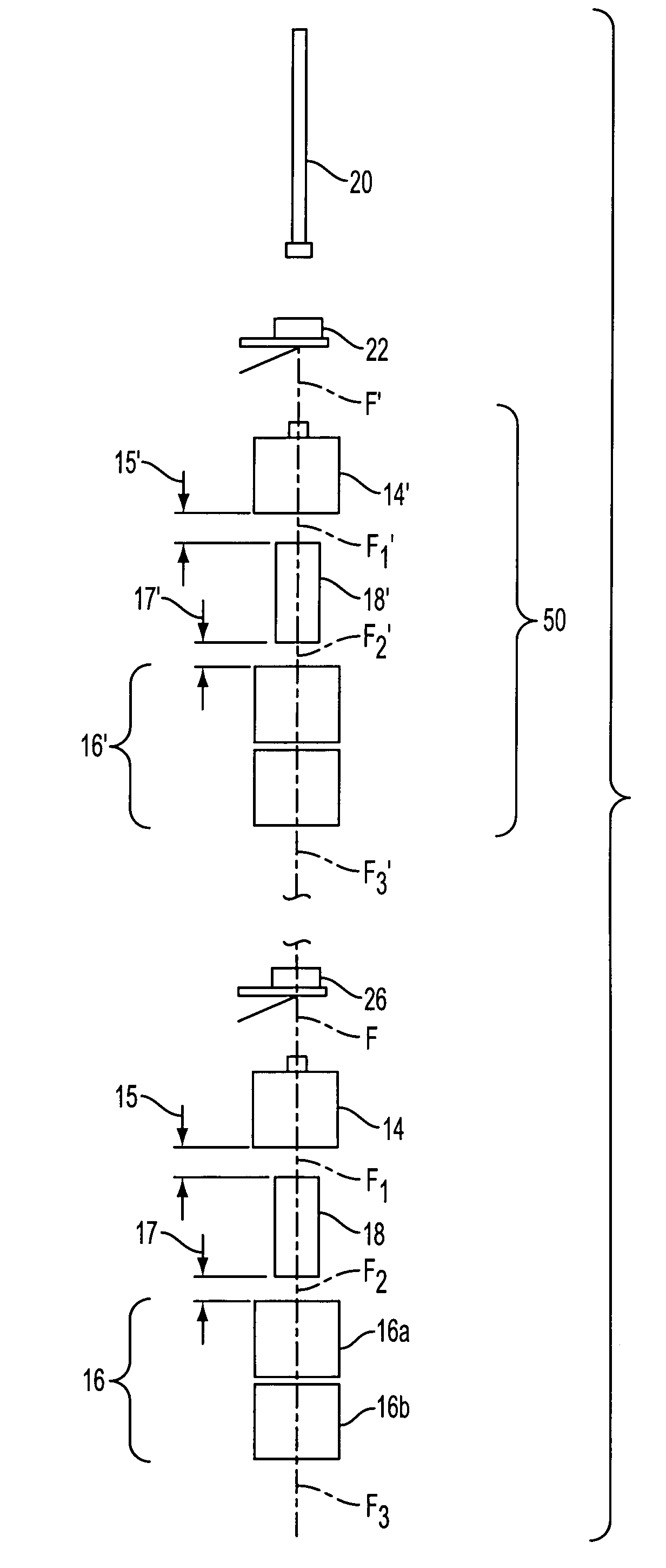
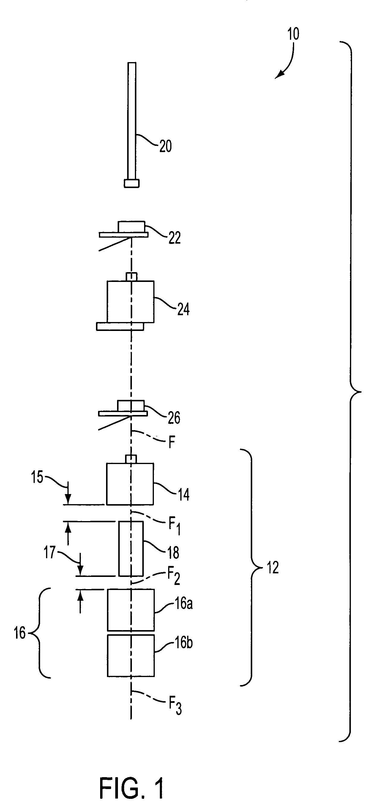
[0036]FIG. 1 shows an apparatus in accordance with the present invention for producing fiber generally indicated as 10. In its broadest sense, the invention consists of a method and apparatus that provides an improved UV curing stage generally indicated as 12 for curing a coated fiber F, comprising at least two fiber coating curing stages 14, 16 and a cooling stage 18.

[0037]As shown, the at least two fiber coating curing stages 14, respond to the coated fiber F, for providing a partially cured coated fiber generally indicated as F1, and further, respond to a cooled partially cured coated fiber generally indicated as F2, for further providing a cured coated fiber generally indicated as F3.

[0038]The cooling stage 18 responds to the partially cured coated fiber F1, for providing the cooled partially cured coated fiber F2. The fiber coating curing stage 14 has one or more UV cure lamps. The fiber coating curing stage 16 has one or more UV cure lamps indicated as 16(a), 16(b). Each of th...

second embodiment

[0046]Turning now to FIGS. 5-9, the present invention will now be discussed. As stated previously, in addition to the benefits from cooling a fiber coating between curing stages (discussed above), the inventor of the present application has determined that spacing and / or the provision of dark-cure time between various curing stages can be beneficial in obtaining a complete fiber coating cure. Dark-cure time is defined as the period immediately following exposure to a UV lamp during which the polymerization reaction proceeds in the absence of initiating irradiation.

[0047]Most existing configurations of UV lamps for curing coatings on optical fiber draw towers (as well as other applications) stack UV lamps together on the spine of the draw tower. This can be seen in FIG. 8. It has been widely considered that the larger the number of the UV lamps used, the more complete the coating cure would become, as the line speed is increased. For example, it has been previously considered that wh...


PUM

PropertyMeasurementUnit
timeaaaaaaaaaa
timeaaaaaaaaaa
timeaaaaaaaaaa

Abstract

The present invention provides a method and apparatus for curing a coated fiber, comprising either two fiber coating curing stages separated by a cooling stage, or two fiber coating curing stages separated by a distinct time interval, or both. One of the two fiber coating curing stages responds to the coated fiber, and provides a partially cured fiber coating. The other of the two fiber coating curing stages responds to the partially cured coated fiber for further curing the coating of the fiber. In one embodiment of the invention, a cooling stage is placed between the two curing stages, while in the other the curing stages are placed a set distance apart such that polymerization of the coating initiated by the first curing stage has time to complete prior to the coating being irradiated by the second curing stage. The cooling stage is used to actively remove heat generated during the cure process from the fiber coating, while the time delay is used to allow complete polymerization to occur before subsequent irradiations. These embodiments of the present invention can be used separately or in combination to achieve optimal fiber coating cure.

Description

BACKGROUND OF THE INVENTION[0001]The present application is a Continuation-in-Part of U.S. application Ser. No. 08 / 784,014, filed on Jan. 15, 1997 now abandoned.FIELD OF THE INVENTION[0002]The present invention relates to an apparatus for producing optical fiber and cable wiring; and, more particularly, relates to an apparatus for producing optical fiber and cable wiring which includes drawing, cooling, coating and curing optical fiber and cable wiring.BRIEF DESCRIPTION OF THE PRIOR ART[0003]In the prior art, there are many different ways to produce fiber, and many different ways to draw, cool, coat and cure optical fiber. For example, U.S. Pat. No. 5,092,264, issued to the instant inventor, describes a device to filter out an infrared component of radiation emitted on the fiber by Ultraviolet (UV) curing lamps for the purpose of reducing the heat put into a fiber coating. The device consists of a double-walled, quartz center tube placed within the UV curing lamps through which the ...

Claims


Application Information

Patent Timeline
Patent Type & Authority Patents(United States)
IPC IPC(8): F26B19/00B05D3/02G02B6/44B05D3/06B29C35/08B29C35/10C03C25/12
CPCB05D3/0209B29C35/10C03C25/12B05D3/067B05D2256/00B29C2035/0827B29L2011/0075
Inventor OVERTON, BOBLI, LING
Owner DRAKA COMTEQ BV
Why Eureka
Try Eureka