Engine fuel injection control method and engine fuel injection control apparatus

a technology of control apparatus and engine fuel injection, which is applied in the direction of electrical control, process and machine control, instruments, etc., can solve the problems of fuel injection not being performed at all, fuel injection may not be injected at all, and conventional engine fuel injection apparatus may not be able to inject a prescribed amount of fuel

Inactive Publication Date: 2008-01-29
NISSAN MOTOR CO LTD
View PDF5 Cites 12 Cited by
  • Summary
  • Abstract
  • Description
  • Claims
  • Application Information

AI Technical Summary

Benefits of technology

[0008]Accordingly, one object of the present invention is to provide an engine fuel injection control method and an engine fuel injection control apparatus which determines time deterioration of the fuel injection apparatus.

Problems solved by technology

The conventional engine fuel injection apparatus may not be able to inject a prescribed amount of fuel, which is set corresponding to an engine operation condition, when a fuel injection apparatus deteriorates over time.
In this circumstance, the fuel injection amount may be decreased or the fuel injection may not be performed at all.
In this case, the engine performances such as the combustion noise and the exhaust emission that are supposed to be improved by controlling the fuel injection amount may deteriorate.

Method used


Image

  • Engine fuel injection control method and engine fuel injection control apparatus
  • Engine fuel injection control method and engine fuel injection control apparatus
  • Engine fuel injection control method and engine fuel injection control apparatus

Examples


Embodiment Construction

[0018]Selected embodiment of the present invention will now be explained with reference to the drawings. It will be apparent to those skilled in the art from this disclosure that the following description of the embodiment of the present invention is provided for illustration only and not for the purpose of limiting the invention as defined by the appended claims and their equivalents.

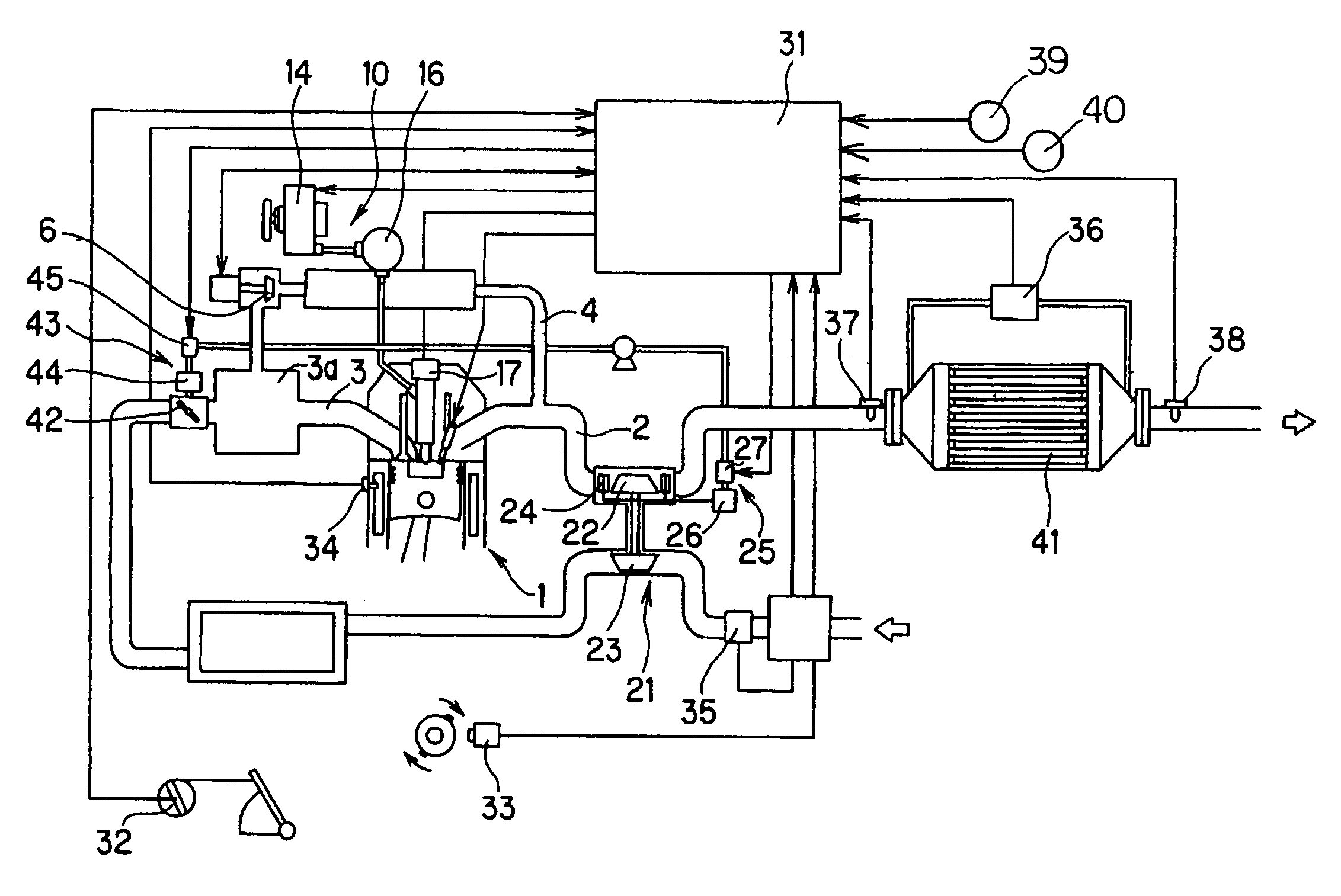
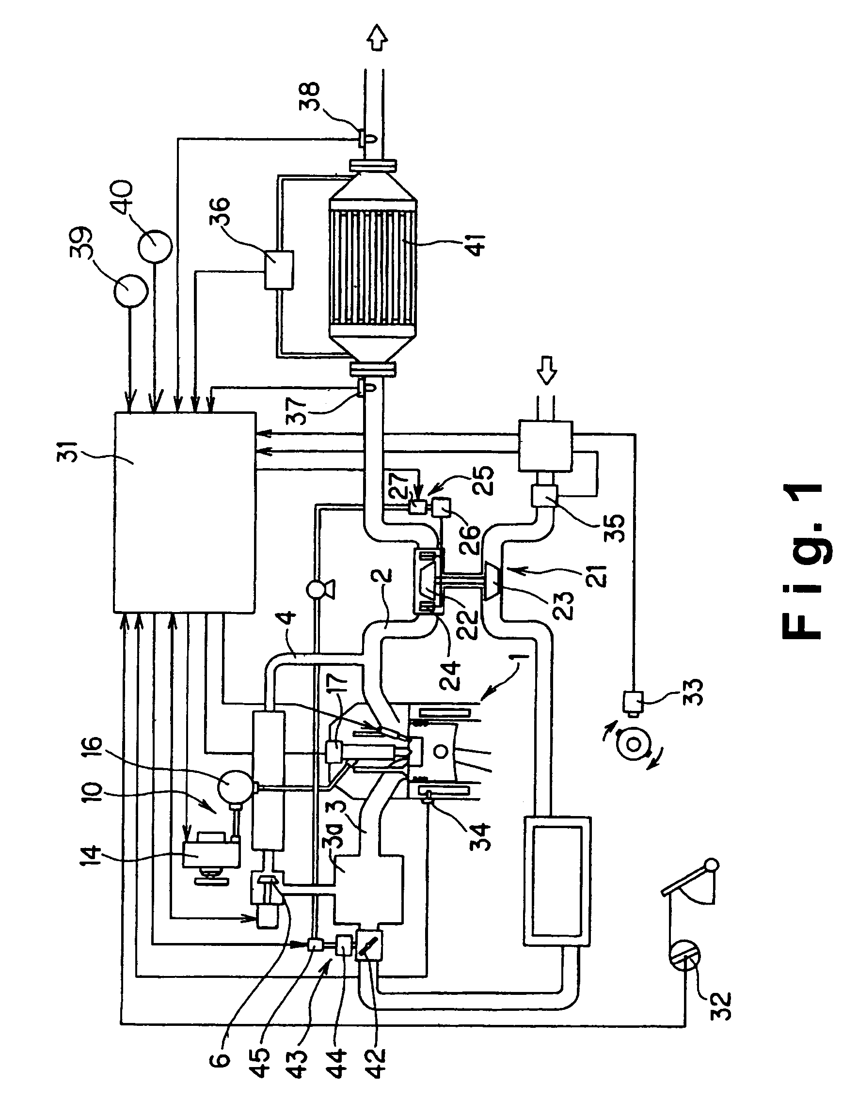
[0019]Referring initially to FIG. 1, an engine fuel injection control apparatus is illustrated in accordance with one embodiment of the present invention. FIG. 1 is an overall schematic diagram of a control system of a vehicle in which the engine fuel injection control apparatus is applied to perform an engine fuel injection control in accordance with the present invention.

[0020]As shown in FIG. 1, the vehicle includes an engine 1, an exhaust passage 2, an intake passage 3, an EGR passage 4, a diaphragm EGR valve 6, a common rail fuel injection device 10, a variable capacity turbocharger 21, and an eng...


PUM


Abstract

An engine fuel injection control apparatus has a parameter setting section, a parameter changing section and a determining section. The parameter setting section is configured to set a parameter of fuel injected into an engine to a first injection parameter to control a state of combustion noise or exhaust emission to a target state when an engine operation condition is in a first operation region. The parameter changing section is configured to change the parameter of fuel injected into the engine from the first injection parameter to a second injection parameter when the engine operation condition remains in the first operation region. The determining section is configured to determine whether or not an actual state of the combustion noise or the exhaust emission of the engine changes when the parameter of fuel injected into the engine is changed from the first injection parameter to the second injection parameter.

Description

CROSS-REFERENCE TO RELATED APPLICATIONS[0001]This application claims priority to Japanese Patent Application Nos. 2005-358684, filed on Dec. 13, 2006, and 2006-237584, filed on Sep. 1, 2006. The entire disclosures of Japanese Patent Application Nos. 2005-358684 and 2006-237584 are hereby incorporated herein by reference.BACKGROUND OF THE INVENTION[0002]1. Field of the Invention[0003]The present invention relates to an engine fuel injection control method and an engine fuel injection control apparatus in which a sufficient amount of a micro-injection corresponding to an engine operation condition can be secured even when a fuel injection apparatus of an engine deteriorates over time.[0004]2. Background Information[0005]Japanese Laid-Open Patent Application Publication No. 2001-207828 discloses a conventional engine-fuel injection apparatus configured and arranged to reduce engine combustion noise and exhaust emission by controlling a fuel injection amount.[0006]In view of the above, ...

Claims


Application Information

Patent Timeline
Patent Type & Authority Patents(United States)
IPC IPC(8): F02M51/00G06F17/00
CPCF02D41/1467F02D41/402F02D41/1446F02D41/1459F02D41/146F02D41/403F02D41/405Y02T10/44Y02T10/40
Inventor OHGA, KIYOSHI
Owner NISSAN MOTOR CO LTD
Why Eureka
Try Eureka