Cutting tool inserts and methods to manufacture

Inactive Publication Date: 2008-01-29
DIAMOND INNOVATIONS INC
View PDF22 Cites 81 Cited by
  • Summary
  • Abstract
  • Description
  • Claims
  • Application Information

AI Technical Summary

Problems solved by technology

Directly brazing PCD or PCBN to carbide is challenging as the braze metal must spread over and bind quite dissimilar materials.
Although the prior art brazing process does reduce the material cost of manufacturing superabrasive inserts, the process, and in particular the brazing operation itself, is labor intensive.
The brazing process is labor intensive because the operator has to pay close attention to the joint interface, i.e., the abrasive tip, the braze interface layer, and the insert body, and reposition the materials, when molten, as necessary to assure good bonding.
A difficulty in the brazing process is that tool materials of different composition or grain size frequently require different brazing conditions, i.e., temperatures, times, braze metal formulations.
PCBN and PCD are known to be difficult to wet with brazes unless active metals, such as Ti or Fe, are incorporated into the metal formula.
They also require higher temperature that may lead to degradation of the superabrasive material.
A further disadvantage of conventionally brazed inserts is that once formed, they cannot be heated above the sublimation or liquidus temperature of the braze metal in subsequent processing steps, such as, for example, chemical vapor deposition (CVD) coating of the insert.
Low melting metals used in braze alloys, e.g., Sn, Z

Method used


Image

  • Cutting tool inserts and methods to manufacture
  • Cutting tool inserts and methods to manufacture
  • Cutting tool inserts and methods to manufacture

Examples


example 1

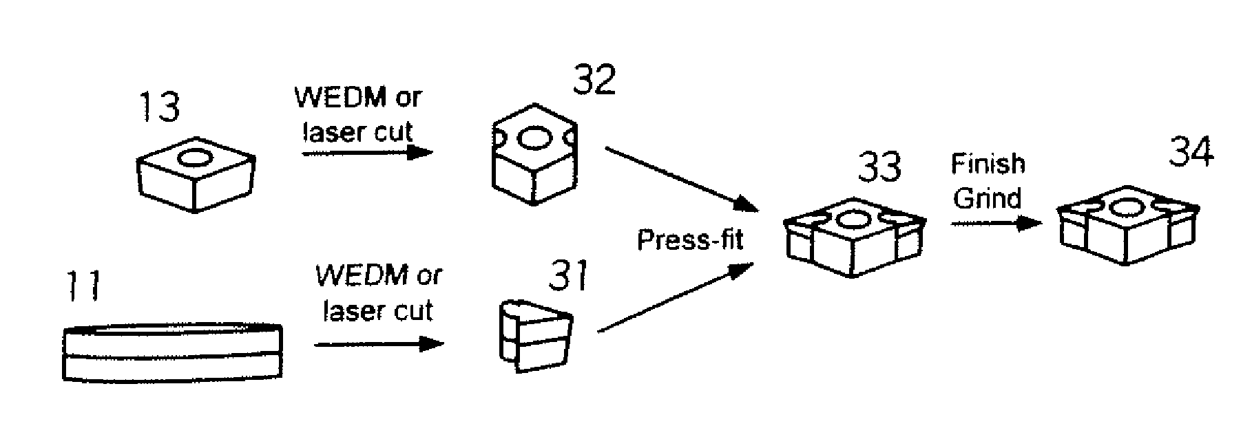
[0071]Two mechanically bonded inserts are prepared by the press-fit embodiment with mating and interlocking dovetail geometry similar to that pictured in FIG. 6A. The abrasive tip material is available from General Electric Company of Worthington, Ohio, as BZN® HTM2100 blank in a carbide supported form with PCBN layer thickness of 0.039″ and the overall thickness of 0.126″. Abrasive tips with an 80° cutting corner and 5 mm leg length are next cut from the blank by WEDM. The male, dovetail shaped mating feature is 0.149″ wide, 0.059″ deep, with 45° corners. The dovetail feature is WEDM cut with a 0.1° taper to facilitate fitting in the female feature of the insert body. The direction of the taper is from PCBN surface to carbide surface, so that the carbide side of the male feature is slightly smaller than the PCBN side. The insert body material is unhardened A2 tool steel with Rockwell Hardness A of 52 to 55. Female featured insert bodies are fabricated by WEDM out of steel plates wi...

example 2

[0075]In this example, several multi-tipped, mechanically bonded inserts of the present invention having mating circular features similar to that depicted in FIG. 7 are prepared using the same procedures and materials as in Example 1 unless indicated otherwise.

[0076]Seven, two-tipped inserts are made from tungsten carbide supported BZN* HTM2100 and insert bodies with two circular offset holes at opposite 80° corners. The offset holes are 0.088″ in diameter and offset from the edge of the insert body by 0.026″. Two mating abrasive tips with taper of 0.3 to 0.5 degrees are press-fit into each insert body to produce two-tipped inserts. A four-tipped insert as illustrated in FIG. 6B is also fabricated with identical geometry by replacing the carbide supported HTM2100 abrasive tips with a specially prepared, solid unsupported version of HTM2100 with a thickness of 0.189″. The exact dimensions of the insert bodies and abrasive tips are of varying levels of interference, in the range of 0....

example 3

[0079]A press-fit assembly taken from EXAMPLE 2 is heated at 800° C. for 2 hrs in flowing argon. The furnace tube is not fully purged of ambient air, so the insert is visibly oxidized but not chipped or cracked. A visual inspection shows that the abrasive tip still being held strongly in the insert body.

[0080]The thermally treated press-fit insert is next tested in the same lathe turning test described in EXAMPLE 1. The wear rate of the thermally-treated press-fit insert is comparable to the unheated press-fit assemblies in Examples 1 and 2, i.e., with no deleterious increase in flank wear, thus demonstrating the feasibility of thermal processing of the novel press-fit insert assembly of the invention.


PUM

PropertyMeasurementUnit
Temperatureaaaaaaaaaa
Forceaaaaaaaaaa
Abrasiveaaaaaaaaaa

Abstract

The present invention relates to cutting tool inserts. A cutting tool insert includes an abrasive tip of a hard material, an abrasive or superabrasive material. A cutting tool insert is bonded to an insert body by mechanical force. The mechanical forces are generated through deformation of mating geometric features on the abrasive tip and insert body.

Description

CROSS-REFERENCE TO RELATED APPLICATIONS[0001]This application claims priority on U.S. Provisional Application Ser. No. 60 / 470,306, filed on May 14, 2003.FIELD THE INVENTION[0002]The present invention relates to cutting tool inserts, wherein an abrasive tip comprising an abrasive / superabrasive material is bonded to an insert body by mechanical forces generated through deformation of mating geometric features on the abrasive tip and insert body.BACKGROUND OF THE INVENTION[0003]Machining, cutting, sawing or drilling tools are often provided with removable inserts comprising conventional materials such as cemented carbides, ceramics (e.g. Si3N4, TiC—Al2O3 composites), and high-speed steel. As depicted in FIG. 1, insert 1 is held firmly and locked into a tool holder 5 by a screw or other clamping mechanism 4. In machining operations, the insert is held in contact with the work piece and eventually wears to a point wherein it requires replacement. Inserts are, by definition, a disposable ...

Claims


Application Information

Patent Timeline
IPC IPC(8): B23B27/16B23B27/14B23P15/28C23C30/00
CPCB23B27/145B23P15/28C23C30/005B23B2205/02B23B2226/125B23B2226/315B23B2226/61Y10T407/27Y10T407/23Y10T407/26B23B2240/28B23B27/14B23B27/16
Inventor WEBB, STEVEN W.EILER, JOSEPH T.
Owner DIAMOND INNOVATIONS INC
Why Eureka
Try Eureka