Acceleration/angular velocity sensor unit

a technology of acceleration/angular velocity and sensor unit, which is applied in the direction of navigation instruments, pedestrian/occupant safety arrangements, instruments, etc., can solve the problems of difficult failure diagnosis of sensors, complicated installation of respective systems 210 to 230 in the vehicle, and worsening of packaging density, so as to improve the vertical precision of z-direction acceleration sensors and the z-axis, improve the packaging density of the substrate, and reduce the size of the acceleration/angular velocity sensor unit

Inactive Publication Date: 2008-02-05
HONDA MOTOR CO LTD
View PDF11 Cites 47 Cited by
  • Summary
  • Abstract
  • Description
  • Claims
  • Application Information

AI Technical Summary

Benefits of technology

[0016]It is an object of the present invention to provide an acceleration / angular velocity sensor unit sensor unit that is fixed relative to an object to which it is mounted and capable of improving a packaging density of a substrate by solving the problem that the packaging density of the substrate is decreased and also further capable of improving a packaging precision of a sensor by solving the problem that the packaging precision of the sensor is worsened.
[0017]Also, it is another object of the present invention to provide an acceleration / angular velocity sensor Unit capable of finding immediately the failure of the X-direction acceleration sensor, the Y-direction acceleration sensor, the Z-direction acceleration sensor, the X-axis angular velocity sensor, the Y-axis angular velocity sensor, and the Z-axis angular velocity sensor, to improve the maintenance performance of the vehicle.

Problems solved by technology

Therefore, there is a drawback with this known design that the installation of respective systems 210 to 230 into the vehicle becomes complicated.
Therefore, a problem exists that the failure diagnosis of the sensors becomes difficult.
As a result, there is such a problem that the worsening of the packaging density on the sensor substrate 202 or the signal processing substrate 205 is brought about.
Also, there is such a problem that reduction in a packaging precision due to the influence of bowing of the substrate, etc. is brought about.

Method used


Image

  • Acceleration/angular velocity sensor unit
  • Acceleration/angular velocity sensor unit
  • Acceleration/angular velocity sensor unit

Examples


Embodiment Construction

[0037]The best mode for carrying out the present invention will be explained with reference to the accompanying drawings hereinafter. In this case, respective drawings are viewed along the direction of reference symbols.

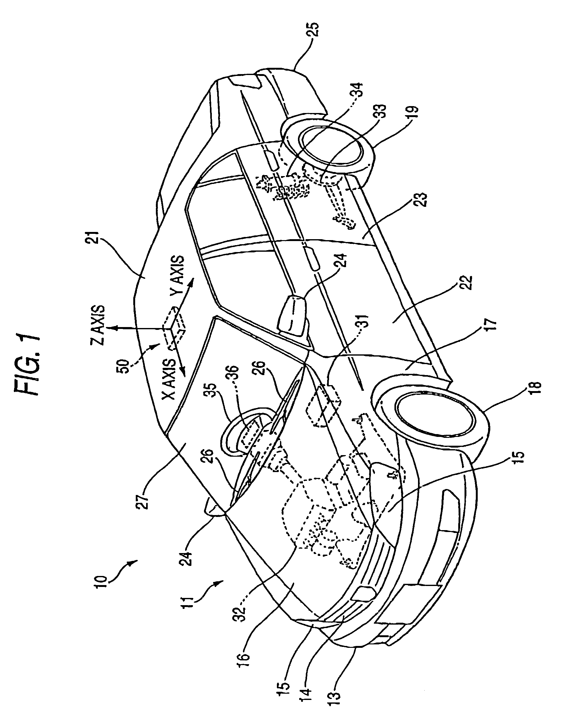
[0038]FIG. 1 is a perspective view of a vehicle that employs an acceleration / angular velocity sensor unit according to the present invention. In FIG. 1, a reference numeral 10 denotes a vehicle, 11 car body, 13 front bumper, 14 front grille, 15 headlamp, 16 bonnet, 17 front fender, 18 front wheel, 19 rear wheel, 21 roof, 22 front door, 23 rear door, 24 door mirror, 25 rear bumper, 26 front wiper, 27 front window, 31 control portion (ECU: Electronic Control Unit), 32 engine, 33 rear brake, 34 rear suspension, 35 power steering, 36 air bag, and 50 acceleration / angular velocity sensor unit (abbreviated as a “sensor unit 50” hereinafter) of the vehicle as the acceleration / angular velocity sensor unit.

[0039]The sensor unit 50 according to the present invention provides th...


PUM


Abstract

A longitudinal G sensor 51 and a roll rate sensor 54 are mounted onto a back surface 61b of a substrate 61 in parallel with an X-axis and a lateral G sensor 52 and a pitch rate sensor 55 are mounted thereon in parallel with a Y-axis, the longitudinal G sensor 51 and the lateral G sensor 52 are positioned thereon in close vicinity to each other, and the roll rate sensor 54 and the pitch rate sensor 55 are positioned thereon in close vicinity to each other, while a vertical G sensor 53 and a yaw rate sensor 56 are mounted onto a surface 61a of the substrate 61 in orthogonal to a Z-axis and also the vertical G sensor 53 and the yaw rate sensor 56 are mounted thereon in close vicinity to each other.

Description

BACKGROUND OF THE INVENTION[0001]The present invention relates to an acceleration / angular velocity sensor unit capable of sensing an acceleration and an angular velocity.[0002]The acceleration / angular velocity sensor unit provides a unit in which the acceleration sensor and the angular velocity sensor are packaged on a substrate and arranged in a small space.[0003]A known acceleration / angular velocity sensor unit is satisfactory in practical use if just the dedicated sensor is incorporated into such unit. For instance, the acceleration sensor or the speed sensor is incorporated if the system is the navigation system, the acceleration sensor for sensing the acceleration in the lateral direction, or the like is incorporated if the system is the sideslip control system, and the steering angle sensor, the angular velocity sensor, or the like is incorporated if the system is the cruise control system.[0004]FIGS. 7A to 7C are block diagrams of the navigation system, the sideslip control s...

Claims


Application Information

Patent Timeline
Patent Type & Authority Patents(United States)
IPC IPC(8): G01C19/00G01P3/44G01P15/18G01P21/00G01P21/02
CPCB60R21/0132B60T8/172G01C21/16B60R2021/01184B60R2021/01327B60T2270/402G01C21/166G01C21/183G01C21/10
Inventor SAITO, KAZUTAKANAKAMUTA, AKIRA
Owner HONDA MOTOR CO LTD
Why Eureka
Try Eureka