
Contamination control system and air-conditioning system of a substrate processing apparatus using the same

a technology of contamination control system and substrate processing apparatus, which is applied in the direction of lighting and heating apparatus, heating types, and separation processes, etc., can solve the problems of reducing the yield and productivity of semiconductor fabricating equipment, affecting the quality of substrate processing equipment, and contaminating the process line for manufacturing parts, etc., to achieve rapid dissolution of contaminants in circulating water and high removal efficiency

Inactive Publication Date: 2008-02-05
SAMSUNG ELECTRONICS CO LTD
View PDF10 Cites 3 Cited by
  • Summary
  • Abstract
  • Description
  • Claims
  • Application Information

AI Technical Summary

Benefits of technology

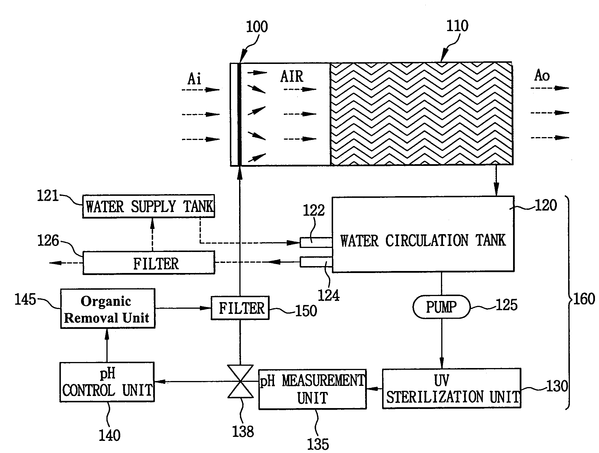
[0018]Exemplary embodiments of the invention include contamination control systems capable of simultaneously removing various contaminants in a flow of air with high removal efficiency by rapidly dissolving the contaminants in circulating water and maintaining the pH of the circulating water.
[0019]Exemplary embodiments of the invention further include air-conditioning systems of a substrate processing apparatus capable of providing clean air without contaminants to a substrate processing apparatus by simultaneously controlling the contaminants with high removal efficiency.
[0023]According to another exemplary embodiment of the present invention, the additive is added to the water that is provided to the contamination control apparatus for removing the contaminants in the air. Therefore, the pH of the water is constantly maintained. As a result, the contamination control apparatus has improved efficiency for removing the contaminants from a flow of air supplied to the contamination control apparatus. Further, the contaminants captured in the water are continuously removed so that the water has enhanced efficiency for capturing contaminants in the air.

Problems solved by technology

Generally, a process line for manufacturing a part, for example a semiconductor device or an electronic article, may be contaminated by various contaminants.
Even a very small amount of contaminants, such as a unit of parts per billion (ppb), reduces the yield and productivity of semiconductor fabricating equipment.
However, the chemical filter is very expensive and short-lived.
Thus, since the chemical filter is periodically exchanged for a new chemical filter, the running cost of the clean air supplying apparatus increases, thereby increasing the cost of the semiconductor device.
Further, since various chemical filters are provided in accordance with various contaminants, maintenance of the chemical filters may be difficult.
This causes continuous use of a disabled chemical filter so that trouble may occur in the semiconductor fabricating process.
When a new AMC appears, a new chemical filter for removing the new AMC is required, and the cost associated with developing the new chemical filter increases the cost of the new filter needed to remove the new AMC.
Further, the AMC in the clean room, which is referred to as an ambient contamination, may be chemically non-visual.
Thus, the AMC may not be studied from the viewpoint of the contamination control technology.
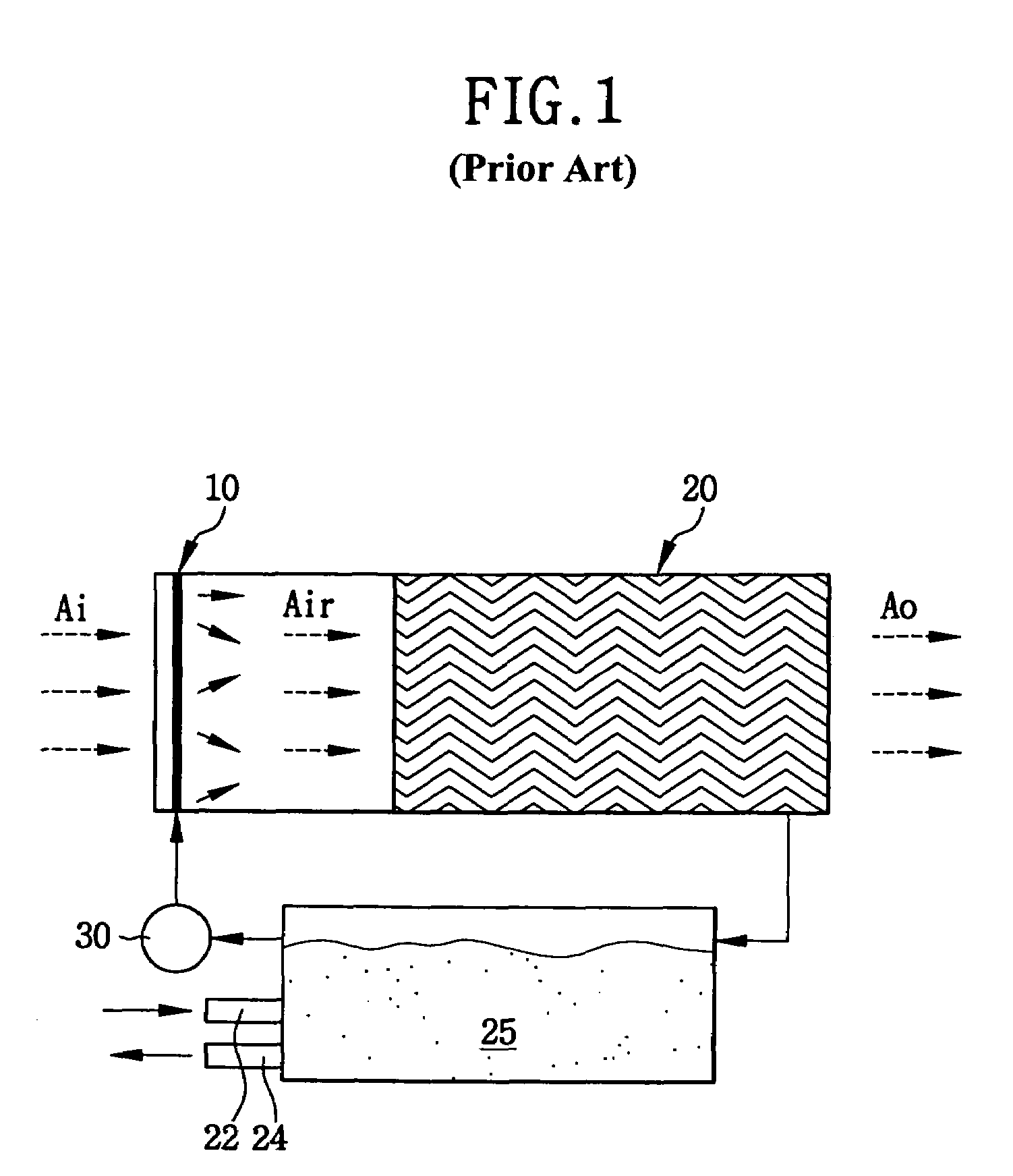
As a result, when the water continues to circulate, the quality of the water deteriorates.
Thus, there is a limit to the amount of contaminants that can be removed using the circulating water.
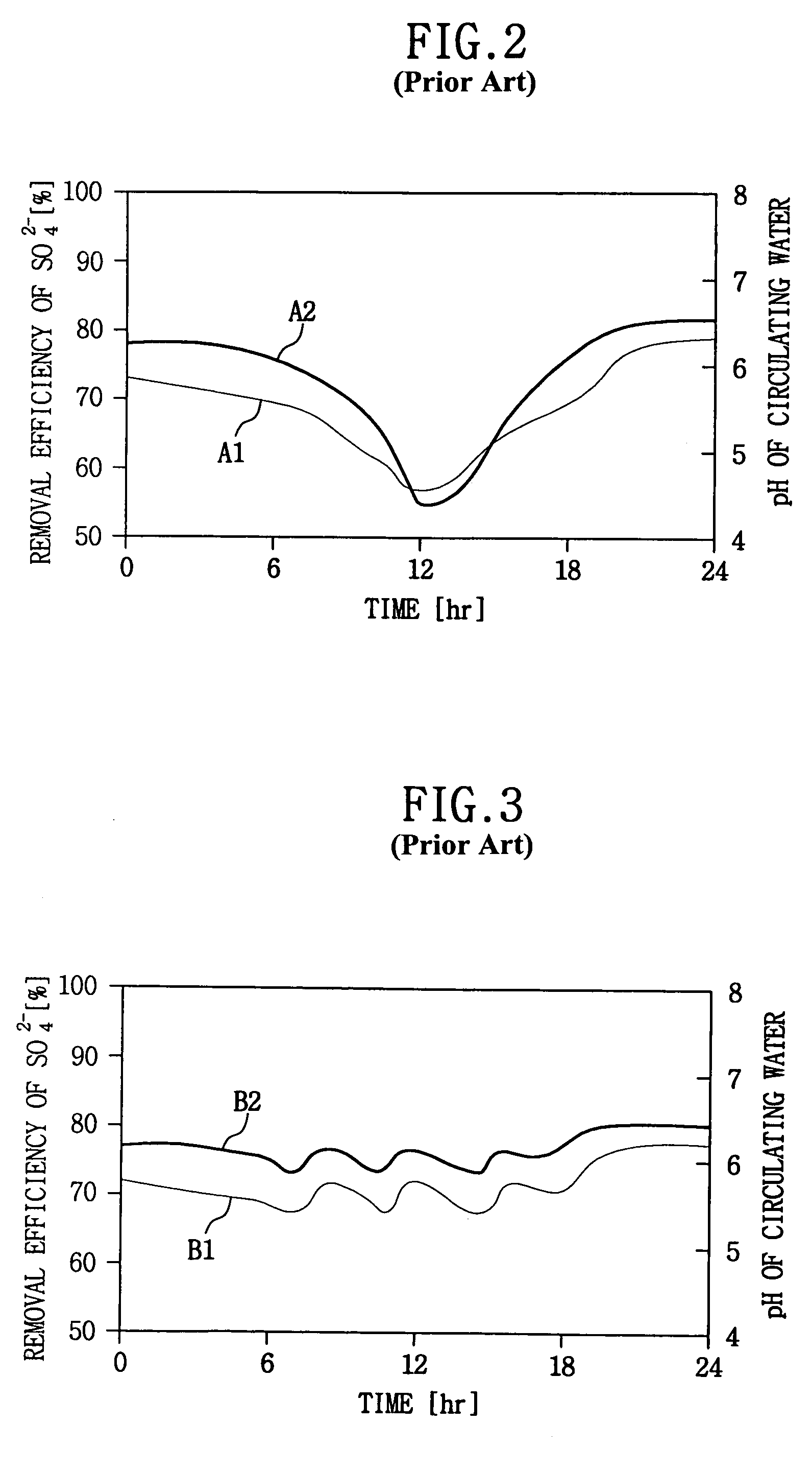
In addition, the pH of the circulating water is lowered by the contaminants such that the circulating water having a low pH may not remove the contaminants from the air.
However, when an amount of the new water is too much, a load cost and a running cost of the pump 30 increase so that the water showering system has an inferior efficiency.
Therefore, the conventional water showering system may not be employed in an air-conditioning system of a piece of equipment used in semiconductor fabrication.

Method used


Image

  • Contamination control system and air-conditioning system of a substrate processing apparatus using the same
  • Contamination control system and air-conditioning system of a substrate processing apparatus using the same
  • Contamination control system and air-conditioning system of a substrate processing apparatus using the same

Examples


Embodiment Construction

[0044]An additive for maintaining the pH of the water absorbs light to create an active species including an electron and a hole. The additive may include a photocatalyst. A photocatalyst reaction is an oxidation-reduction reaction of the electron / hole that is created by applying a sufficient amount of energy to a material activated by the photocatalyst to cause electrons to bridge a gap in the energy band. A high oxidation-reduction potential obtained from the catalyst purifies most environmental contaminants so that the photocatalyst is used for removing contaminants, for example NOx, SOx and VOC, within a flow of air. In addition, the photocatalyst may also remove an unpleasant odor and act as an antifungal agent.

[0045]A catalyst functions as a material that changes a reaction rate or initiates a reaction without being used up in a chemical reaction. The photocatalyst is a kind of catalyst. Light energy is applied to the photocatalyst to perform the above functions. Examples of a...


PUM

PropertyMeasurementUnit
sizeaaaaaaaaaa
sizeaaaaaaaaaa
pHaaaaaaaaaa

Abstract

An air-conditioning system of a substrate processing apparatus includes an air inlet line for providing air to a clean room. A contamination control apparatus for removing contaminants in the air is connected to the air inlet line. A controller controls temperature and humidity of the air without the contaminants. An air outlet line provides the air having the controlled temperature and humidity to a substrate processing chamber that is disposed in the clean room. The contamination control apparatus includes a spray unit having at least one nozzle that sprays water. At least one eliminator that traps the water for capturing contaminants in the air and drops the trapped water into a tank. A water circulation unit provides the water that includes an additive for controlling pH of the water to the spray unit.

Description

CROSS-REFERENCE TO RELATED APPLICATION[0001]This application claims priority to Korean Patent Application No 2003-44800, filed on Jul. 3, 2003, which is incorporated herein by reference in its entirety.BACKGROUND OF THE INVENTION[0002]1. Field of the Invention[0003]The present invention relates, generally, to a contamination control system. More particularly, the present invention relates to a contamination control system for simultaneously and efficiently controlling various contaminants and an air-conditioning system of a substrate processing apparatus using the contamination control system.[0004]2. Description of the Related Art[0005]Generally, a process line for manufacturing a part, for example a semiconductor device or an electronic article, may be contaminated by various contaminants. Even a very small amount of contaminants, such as a unit of parts per billion (ppb), reduces the yield and productivity of semiconductor fabricating equipment. Thus, it is required to provide a ...

Claims


Application Information

Patent Timeline
Patent Type & Authority Patents(United States)
IPC IPC(8): B01D47/00B01D53/14H01L21/02B01D53/78F24F8/133F24F8/142
CPCB01D53/14B01D53/78F24F3/161B01D2255/802B01D2257/106B01D2257/302B01D2257/404B01D2257/406B01D2257/70F24F2003/1617F24F2006/006Y02A50/20F24F8/117F24F3/167F24F8/133F24F8/142H01L21/02
Inventor HWANG, TAE-JINYANG, JAE-HYUNHWANG, JUNG-SUNGKIM, HYUN-JOONAHN, YO-HAN
Owner SAMSUNG ELECTRONICS CO LTD
Learn More