
System for sensing riser motion

a technology of riser motion and motion detection, applied in the direction of sealing/packing, instruments, borehole/well accessories, etc., can solve the problems of low displacement and force, combined stress, tensioner loss, static solution does not take into account any dynamics, and is not as accurate for the overall analysis, and the data to be provided to the computer system, however, has proved more problemati

Inactive Publication Date: 2008-02-12
VETCO GRAY
View PDF9 Cites 89 Cited by
  • Summary
  • Abstract
  • Description
  • Claims
  • Application Information

AI Technical Summary

Benefits of technology

Enables real-time, accurate management of riser systems across all operational modes, including installation, drilling, non-drilling, production, and retrieval, by providing highly accurate riser joint angles and dynamic information, reducing the risk of vortex-induced vibrations and enhancing operational safety and efficiency.

Problems solved by technology

A problem presented by offshore hydrocarbon drilling and producing operations conducted from a floating platform or vessel is the need to establish a sealed fluid pathway between each borehole or well at the ocean floor and the work deck of the vessel at the ocean surface.
The operational constraints to be considered are drilling modes, upper and lower displacements and forces, combined stresses, and tensioner losses.
The static solution does not take into account any dynamics and is not as accurate for the overall analysis of the riser system, but can provide current and steady state loading information.
Obtaining data to provide to the computer systems, however, has proved more problematic.
Especially regarding drilling operations, system integration has been difficult due to the insular nature of the different control systems on the drilling rig.
The operator interfaces currently in use have inherent accuracy limitations due to low update rates and do not capitalize on the importance of lower flex joint angle (“LFJA”) / upper flex joint angle (“UFJA”) differential, nor the importance of modeling the dynamic shape of the riser.
Current systems of monitoring ball / flex joint angle values do not provide riser managers sufficient data to properly maintain such operational parameters.
The systems were, however, originally designed to support drilling operations, not riser management systems, and are not suitable as a basis for riser analysis because they provide only a limited set of measurements, and typically only for the lower flex joint.
Current systems generally provide only static accuracy.
That is, current systems generally only provide a static lower flex joint angle of inclination, values of which are affected by lateral acceleration, and which does not allow for real-time management of the riser system.
Thus, such systems are difficult to integrate with other more globally based systems.
This system, however, does not provide dynamic angular position and orientation of the riser.
Further, this system has not been shown to be practical because each module is individually connected to the data transmission cable through individual cable leads along the length of the data transmission cable.
In either scenario, the procedure is rather labor-intensive and requires disruption of the drilling operation and / or the management of the riser.

Method used


Image

  • System for sensing riser motion
  • System for sensing riser motion
  • System for sensing riser motion

Examples


Embodiment Construction

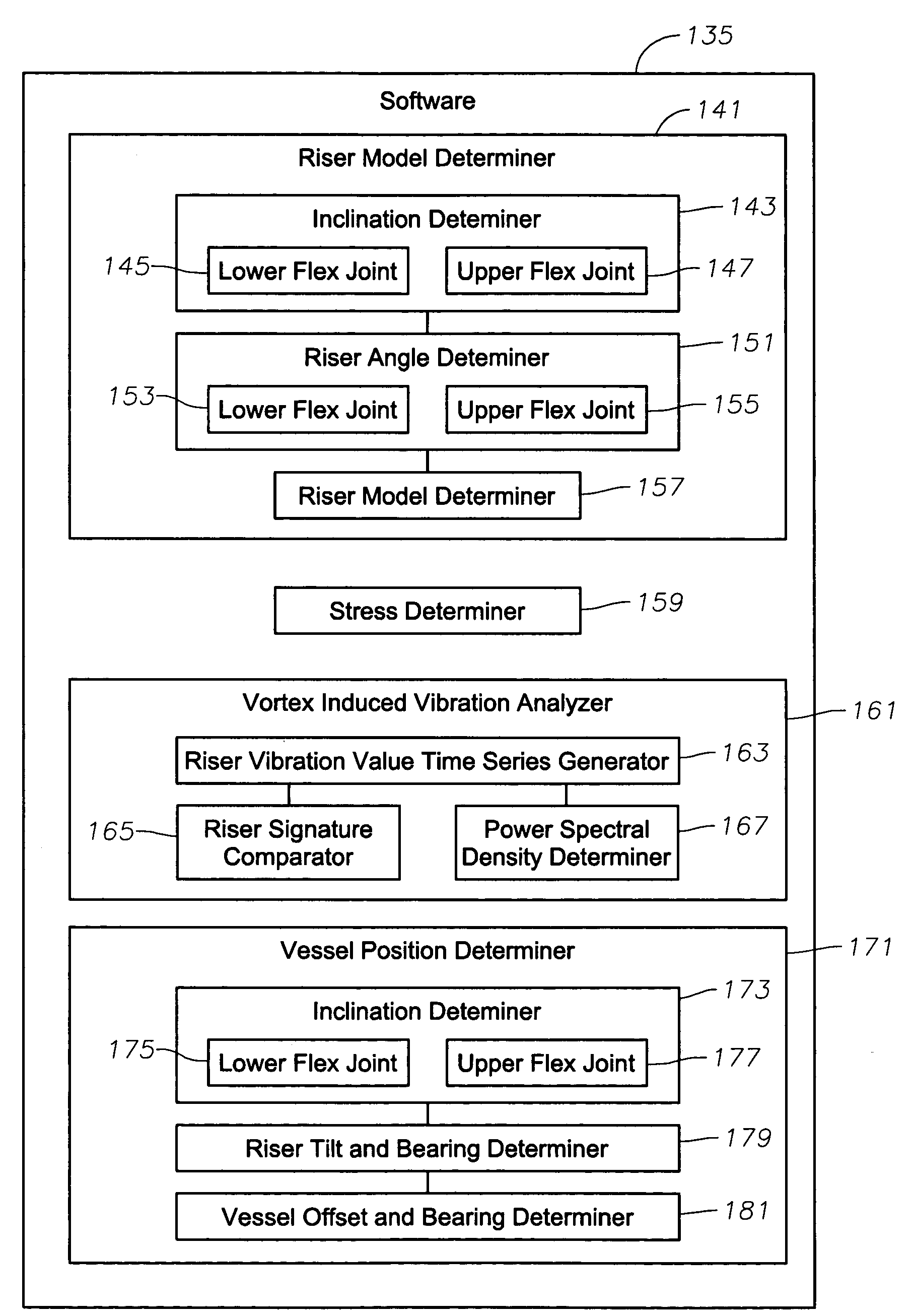
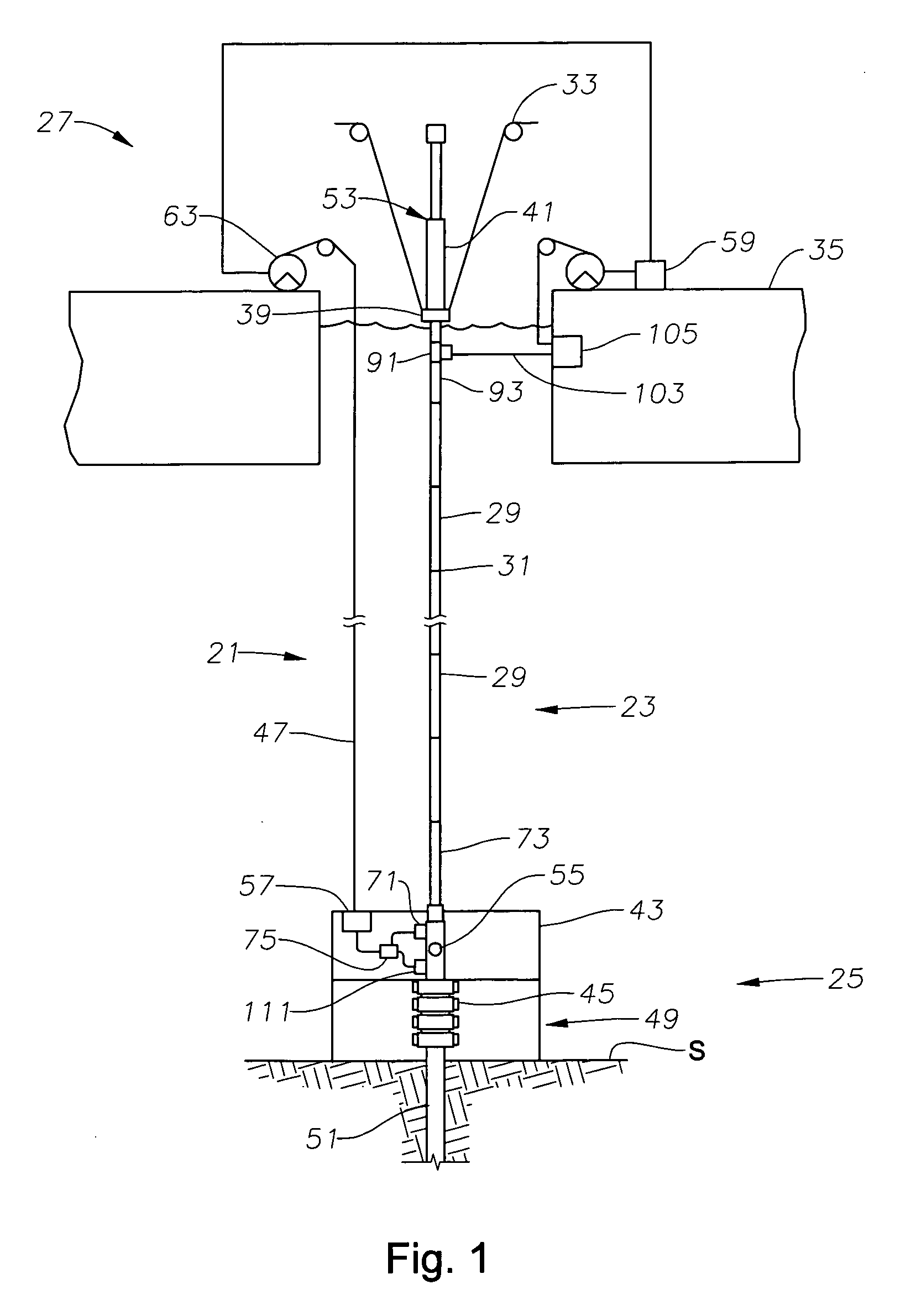
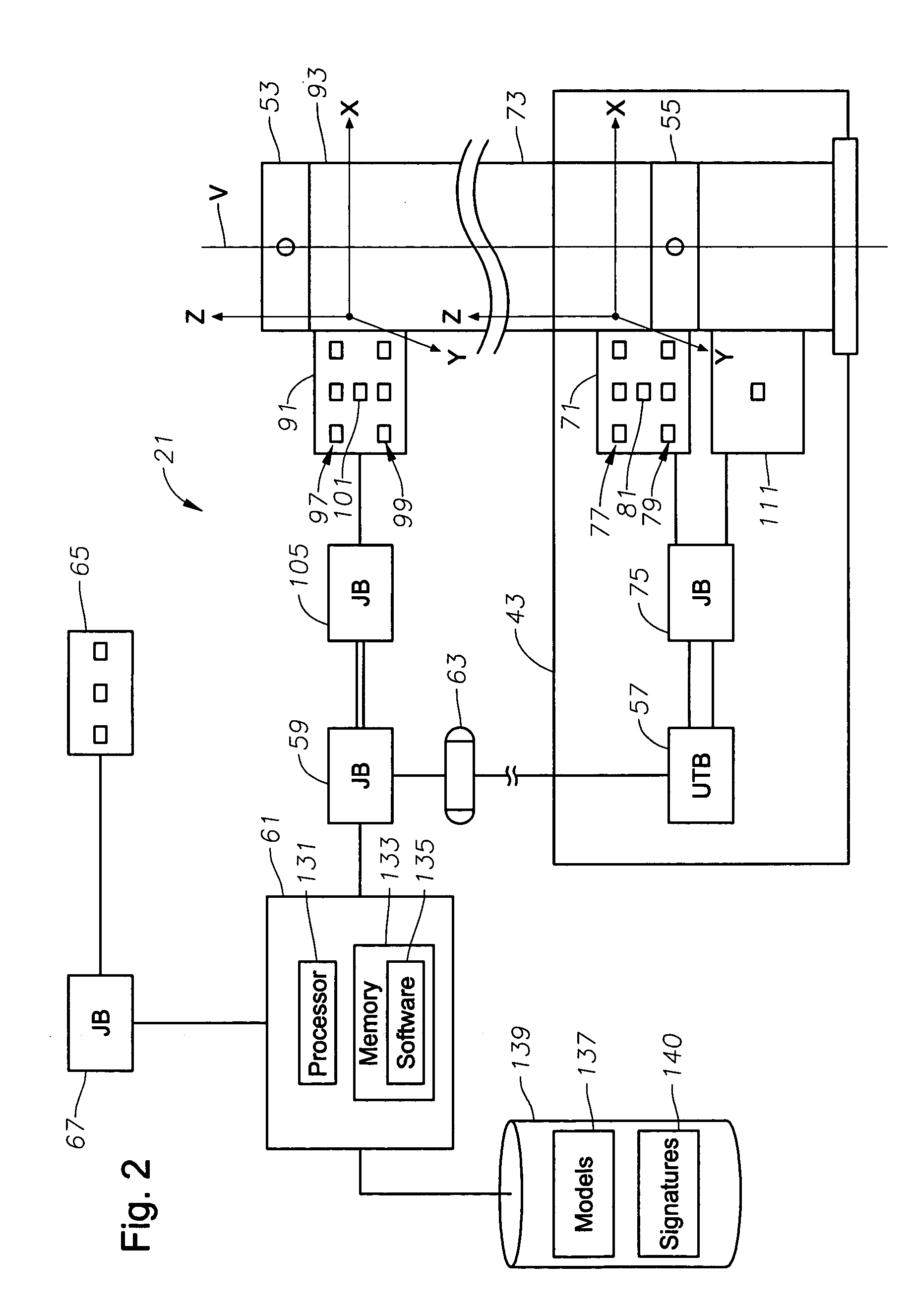
[0033]The present invention will now be described more fully hereinafter with reference to the accompanying drawings which illustrate embodiments of the invention. This invention may, however, be embodied in many different forms and should not be construed as limited to the illustrated embodiments set forth herein. Rather, these embodiments are provided so that this disclosure will be thorough and complete, and will fully convey the scope of the invention to those skilled in the art. Like numbers refer to like elements throughout, and the prime notation, if used, indicates similar elements in alternative embodiments.

[0034]Referring to FIGS. 1 and 2, embodiments of the present invention generally provide an offshore drilling and / or production system 21 including a riser monitoring assembly for monitoring and managing a drilling riser pipe 23 extending between subsea well equipment 25, such as, for example, the illustrated subsea wellhead, and a floating vessel, such as, for example, ...


PUM


Abstract

A riser monitoring assembly is provided to monitor and manage a riser extending between subsea well equipment and a floating vessel. A riser measurement instrument module is connected adjacent a selected portion of the riser provides dynamic orientation data for the selected portion of the riser. A computer having a memory associated therewith and riser system analyzing management software stored thereon is in communication with the riser measurement module to process data received therefrom. The riser monitoring assembly can utilize real-time orientation data for the selected portion of the riser to analyze the riser dynamic behavior, to determine a model of the real-time structure of the riser, to determine and manage the existence of vortex induced vibration, to determine and manage riser stress levels, to manage riser inspection and riser maintenance, and to supplement determination and management of the position of the vessel.

Description

BACKGROUND OF THE INVENTION[0001]1. Field of the Invention[0002]This invention relates to riser management systems. More particularly, this invention relates to a system, an apparatus, and related methods for sensing riser dynamics.[0003]2. Brief Description of the Related Art[0004]A problem presented by offshore hydrocarbon drilling and producing operations conducted from a floating platform or vessel is the need to establish a sealed fluid pathway between each borehole or well at the ocean floor and the work deck of the vessel at the ocean surface. This sealed fluid pathway is typically provided by a drilling riser system. Drilling risers, which are utilized for offshore drilling, extend from the drilling rig to a blowout preventer (BOP) and Lower Marine Riser Package (LMRP), which connect to a subsea wellhead. Production risers extend from a surface vessel to a subsea wellhead system.[0005]The drilling riser, for example, is typically installed directly from a drilling derrick on...

Claims


Application Information

Patent Timeline
Patent Type & Authority Patents(United States)
IPC IPC(8): E21B29/02E21B43/00G01C17/00G01C19/00G01C9/00G06F15/00
CPCE21B19/004E21B44/00B63H25/42
Inventor ALLEN, JOHNPINTO, ANTONIO J.
Owner VETCO GRAY
Learn More