Device and method for optical spectroscopy

Inactive Publication Date: 2008-02-12
CAMPUS TECH
View PDF4 Cites 19 Cited by
  • Summary
  • Abstract
  • Description
  • Claims
  • Application Information

AI Technical Summary

Benefits of technology

[0036]The performance capability of the apparatus and of the method described in the following can be substantially improved if the relative phase position of the part rays can be suitably influenced. This can be done, for instance, by the use of a mirror which is linearly displaceable over a distance in the order of magnitude of the wavelen

Problems solved by technology

However, above all the mechanical components for the setting of the optical path lengths by displaceable mirrors or tiltable mirror pairs are technically demanding here.
The performance capability of Fourier transform spectrometers exceeds

Method used


Image

  • Device and method for optical spectroscopy
  • Device and method for optical spectroscopy
  • Device and method for optical spectroscopy

Examples


Embodiment Construction

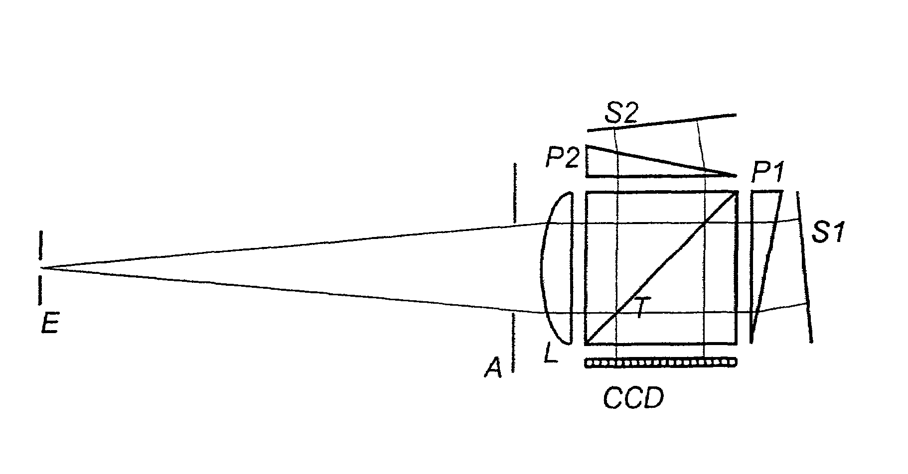
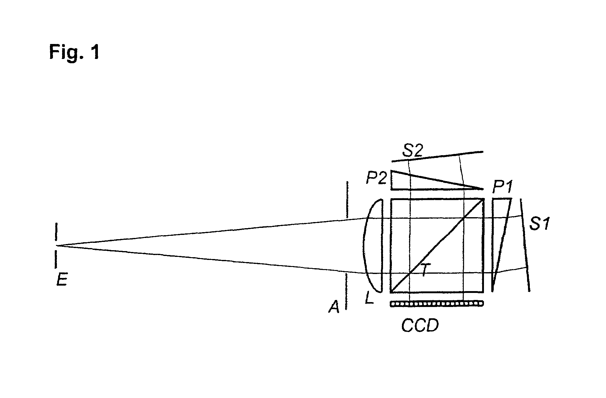
[0038]FIG. 1 shows a variant of an apparatus of the invention to generate the interference pattern starting from a setup of the kind of a Michelson interferometer. A CCD serves as the detector, while the dispersive elements are designed as prisms. The setup does not require any moving elements with the exception of the adjustment. The light incident through the entrance opening E and an aperture diaphragm A is first collimated by a lens L and then split by the beam splitter T. The part rays are reflected by the mirrors S1 or S2, recombined by T and reach the spatially resolving detector CCD. The part rays thereby pass through the respective prisms P1 or P2 twice and are thereby influenced in dependence on the wavelength. The interference pattern resulting at the detector therefore shows a great dependence on the wavelength of the incident light.

[0039]Depending on the dimensioning and the adjustment of the apparatus, different spectral ranges can be detected with different resolution...


PUM


Abstract

The invention relates to an apparatus for optical spectroscopy having means to produce an interference pattern and having a spatially resolving detector which can record the interference pattern produced. In accordance with the invention, the wavefronts of at least one of the part rays involved in the interference pattern is influenced in dependence on the wavelength by spectrally dispersive or diffractive optical elements.

Description

BACKGROUND OF THE INVENTION[0001]The present invention relates to an apparatus and method for optical spectroscopy.[0002]Optical spectrometers can be divided into dispersive or diffractive spectrometers and Fourier transform spectrometers.[0003]Dispersive (prismatic) spectrometers or diffractive (grating) spectrometers break down the incident light ray into its spectral components by the wavelength dependency of an angle of diffraction or of an angle of reflection. The different spectral components are thereby spatially separated and the spectral component to be determined can be selected (monochromator). The recording of a spectrum then takes place with the aid of moving parts by the different spectral components being successively selected and measured.[0004]Monochromators are most frequently used which have a Czerny-Turner ray path, i.e. which have a rotatable plano grating between an entrance gap and an exit gap and mutually independent collimator mirrors or collector mirrors.[0...

Claims


Application Information

Patent Timeline
IPC IPC(8): G01B9/06G01J3/28G01J3/30G01J3/45G01J3/453G01J3/457G01J9/02
CPCG01J3/453G01J3/457G01J9/02G01J2003/2866
Inventor WEITZEL, THILO
Owner CAMPUS TECH
Why Eureka
Try Eureka