Compact high resolution imaging apparatus

a high-resolution, compact technology, applied in the field of optical mapping apparatus, can solve the problems of high mechanical stability, loss, and re-injection of signals from single-mode optical fibers, and achieve the effect of low loss and high mechanical stability

Active Publication Date: 2008-02-12
OPTOS PLC
View PDF13 Cites 56 Cited by
  • Summary
  • Abstract
  • Description
  • Claims
  • Application Information

AI Technical Summary

Benefits of technology

[0025]Overall, the invention sets out a simplified, low cost configuration easy to be assembled in series in a factory, in a very compact format.
[0030]In another embodiment, the optical source is made of two sources, a first low coherence source to generate the OCT image and a second optical source, whose wavelength is advantageously chosen to maximize the sensitivity of the photodetector used in the confocal receiver unit.
[0038]In order to implement a compact apparatus configuration, no external phase modulator is employed for creating the carrier of the OCT signal. This allows the reference path to be continuous in optical fiber, for low losses and high mechanical stability. Therefore, in the T-scan, B-scan or C-scan regimes of operation, the signal is encoded based on the phase modulation only, created by the movement of the transverse scanning means along the T-scan direction which determines the line in the raster of the B-scan or C-scan image, movement which determines modulation of the interference signal.

Problems solved by technology

This is characterized by the disadvantage that the signal has to be extracted from single mode optical fiber and reinjected back into the same or a different single mode optical fiber.
This procedure introduces losses and requires specialized high accuracy and high mechanical stability 3D stages for launching light into a single mode fiber.
In a series assembly line in a factory, such a configuration would require significant assembly time and the final product would be expensive.
Such a grouping and assembly has the added disadvantage that a fiber loop is required to connect the stage with the rest of the OCT system.
When the stage moves, vibrations are induced in the fiber loop which leads to noise.
Also, the polarization of the light propagating down the fiber link may change due to the alteration in the spatial distribution of radiation within the fiber cord, which leads to reduction in the visibility and signal to noise ratio.
Such a solution requires an expensive light source and expensive polarization maintaining fiber in order to avoid noise generation in the fiber and changes in the polarization due to fiber cord being shaped during the depth scanning.
Such modulator is expensive, ads losses, reduces the efficiency in using the signal and introduces dispersion which deteriorates the depth sampling profile of the OCT.
As another disadvantage, during the stage movement, the focus position slips away from the coherence gate position, given by the point in the volume of the object, where the optical path difference in the interferometer is zero.
The longer the depth scanning, the larger the difference between the focus and the coherence gate point, with disadvantageous reduction in the signal strength.
These solutions however, require mechanical synchronism of elements or adjustment of ratios of focal lenses or movement of a bubble elastic lens respectively, with the consequence limitation in speed.
However, the method uses a mirror which redirects high power to the optical source, and it is known that low coherence source are prone to noise in the presence of feedback.
The movement employs elements in both object and reference arm which makes the method cumbersome to implement.
This requires stable mechanical fixtures, low vibrations and the method cannot be implemented in fiber version.

Method used


Image

  • Compact high resolution imaging apparatus
  • Compact high resolution imaging apparatus
  • Compact high resolution imaging apparatus

Examples


Embodiment Construction

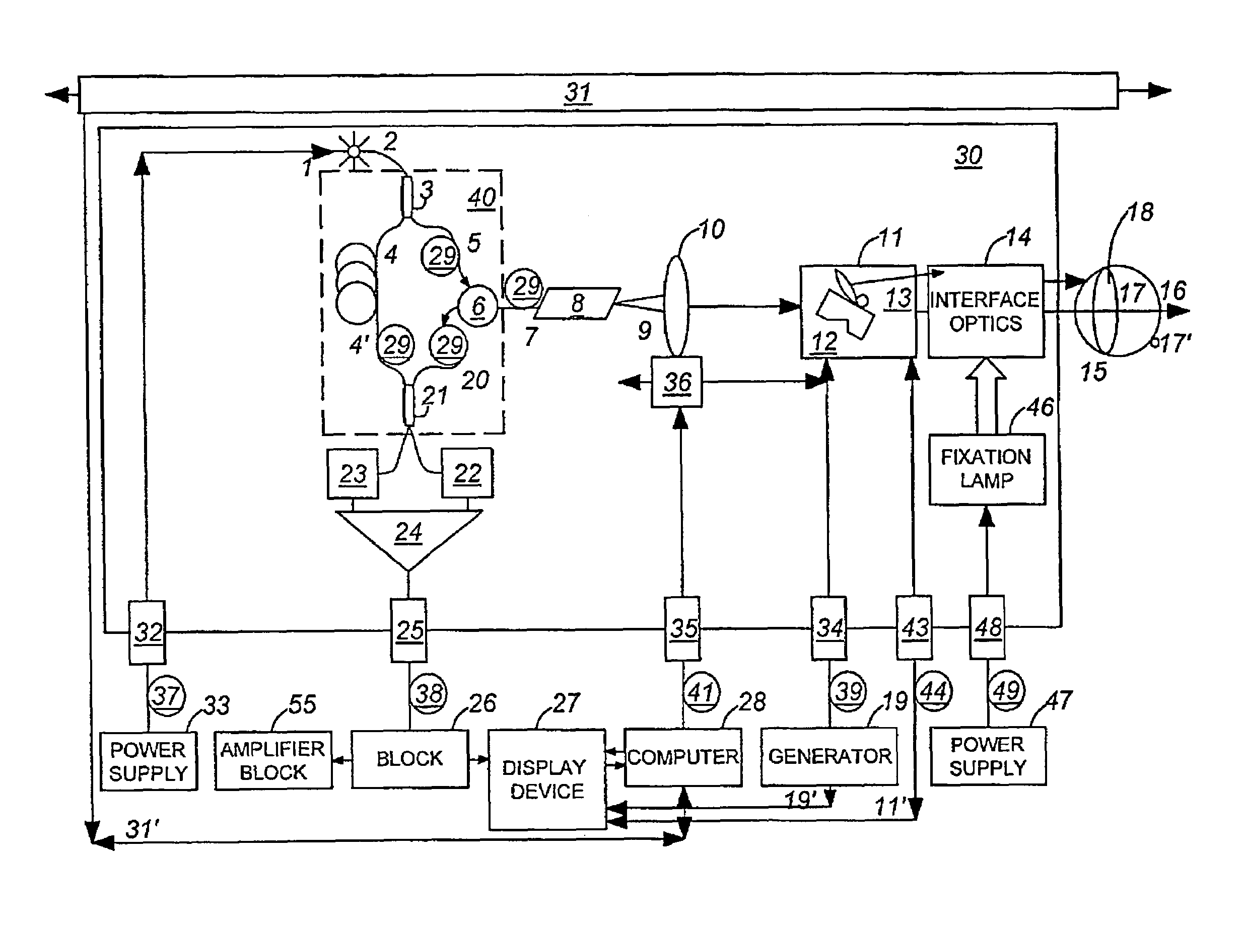
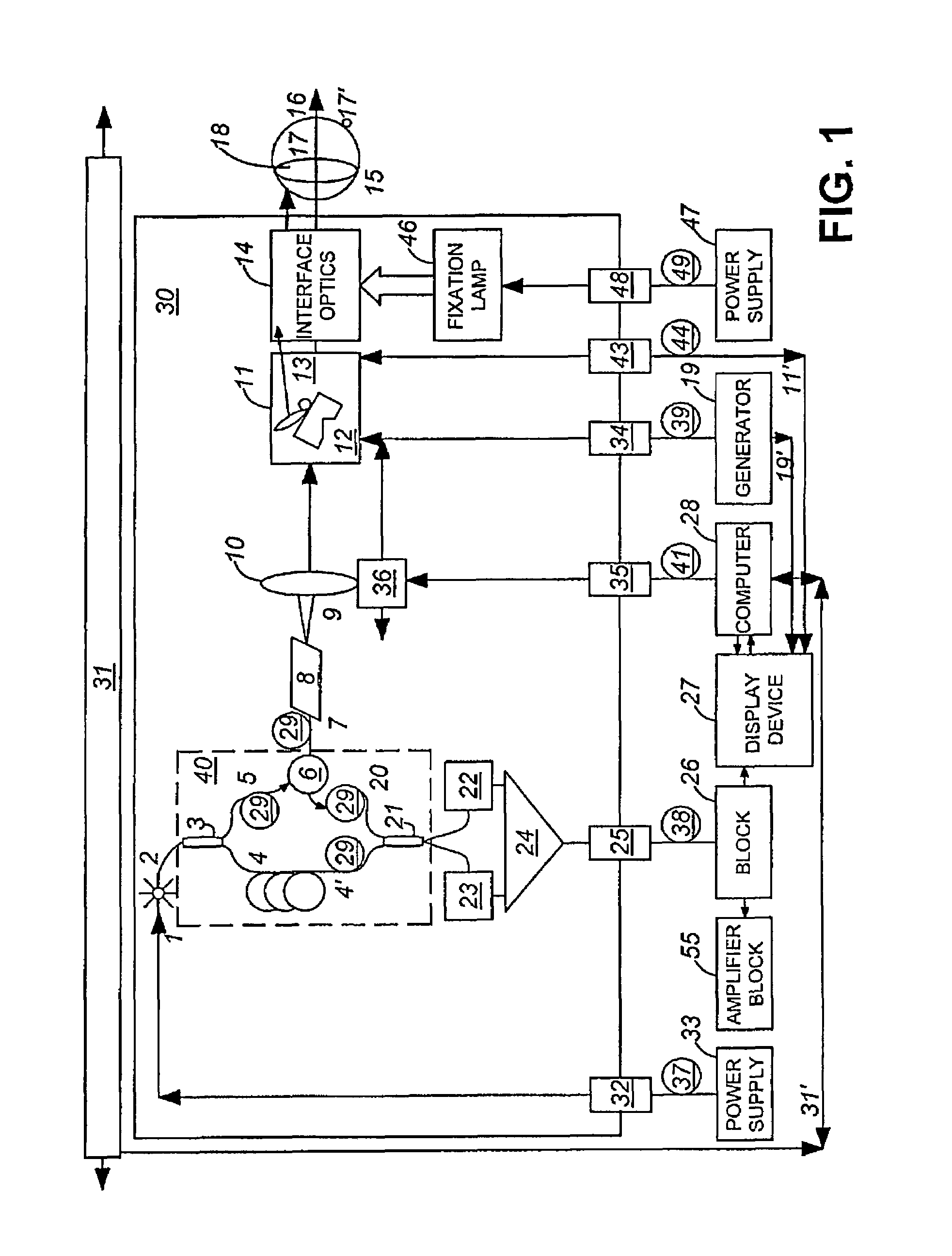
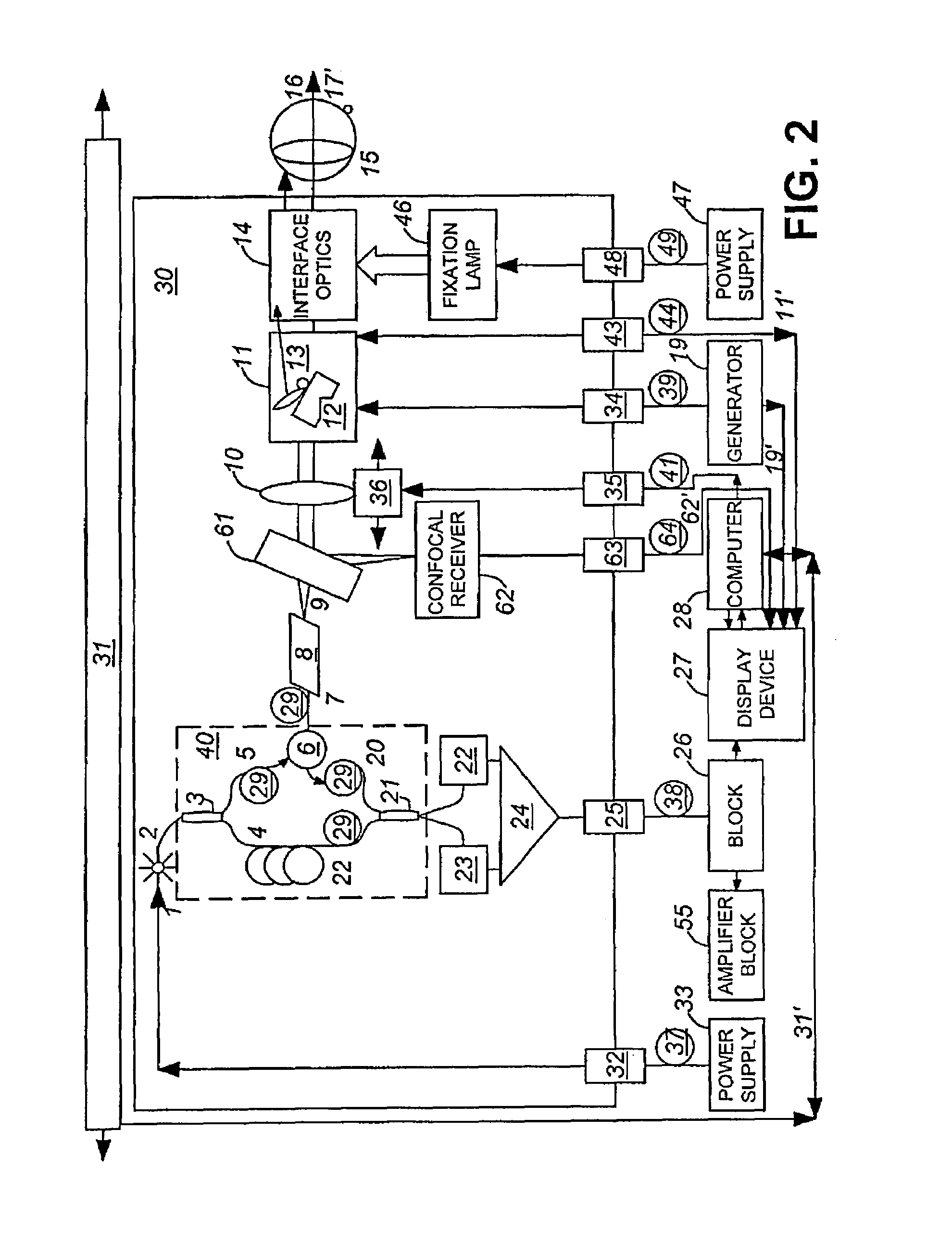
[0049]Various features of the present invention, as well as other objects and advantages attendant thereto, are set forth in the following description and the accompanying drawings in which like reference numerals depict like elements.

[0050]An OCT device may involve and make use of techniques known in the art and described in GB patent(Younguist Davies) no. 8611055; U.S. Pat. No. 5,459,570, U.S. Pat. No. 5,321,501, U.S. Pat. No. 5,491,524, U.S. Pat. No. 5,493,109, U.S. Pat. No. 5,365,335, U.S. Pat. No. 5,268,738, and U.S. Pat. No. 5,644,642 and U.S. Pat. No. 5,975,697 (Podoleanu), which are herein incorporated by reference. These devices can be constructed in bulk or optical fiber, and have means for transversally scanning the target, means for longitudinal scanning of the reference path length, means for phase modulation, means for controlling the polarization stage as bulk or fiber polarizer controllers, and have means for compensating for dispersion. In embodiments of the present...


PUM


Abstract

An optical coherence tomography (OCT) apparatus includes an optical source, an interferometer generating an object beam and a reference beam, a transverse scanner for scanning an object with said object beam, and a processor for generating an OCT image from an OCT signal returned by said interferometer. At least the optical source, the interferometer, and the scanner are mounted on a common translation stage displaceable towards and away from said object. A dynamic focus solution is provided when the scanner and a folded object path are placed on the translation stage.

Description

FIELD OF THE INVENTION[0001]The present invention relates to an optical mapping apparatus, and in particular to an apparatus which can be used to supply images from essentially transparent objects or tissue in general and from the anterior chamber of the eye in special.BACKGROUND OF THE INVENTION[0002]In the description which follows, reference is made primarily to the eye and the anterior chamber of the eye as the object. This is to be understood as merely exemplary to assist in the description and not as a restriction. Where the term “eye” is used, a more general transparent and scattering object or organ may be sought instead.[0003]Low coherence interferometry is an absolute measurement technique which allows high resolution ranging and characterisation of optoelectronic components.as presented in the papers S. A. Al-Chalabi, B. Culshaw and D. E. N. Davies, “Partially coherent sources in interferometric sensors“, First International Conference on Optical Fibre sensors, 26-28 Apr....

Claims


Application Information

Patent Timeline
Patent Type & Authority Patents(United States)
IPC IPC(8): G01B11/02G01B9/02A61B3/10A61B3/12A61B5/00G01B11/00G01B11/24G01J1/00G02B23/24
CPCA61B3/102G01B9/0203G01B9/02091G01B9/02049G01B9/02063G01B2290/70G01B2290/65G01B2290/35A61B3/12G01B9/02
Inventor PODOLEANU, ADRIAN GH.ROGERS, JOHN A.
Owner OPTOS PLC
Why Eureka
Try Eureka