
Electric candle flame simulator

Inactive Publication Date: 2008-02-19
SMITH DAVID ERIC
View PDF29 Cites 37 Cited by
  • Summary
  • Abstract
  • Description
  • Claims
  • Application Information

AI Technical Summary

Benefits of technology

[0004]The complex light intensity pattern creates a perceptually real and pleasing visual effect upon the human eye, much like that created by the flickering of a real combustion flame and employs other than random or pseudo random intensity patterns which typically appear perceptually less real than the electrical simulation provided.

Problems solved by technology

Establishment and maintenance of a real combustion flame can be inconvenient and can create a significant safely risk to people and things located near it.

Method used


Image

  • Electric candle flame simulator
  • Electric candle flame simulator
  • Electric candle flame simulator

Examples


embodiment 100

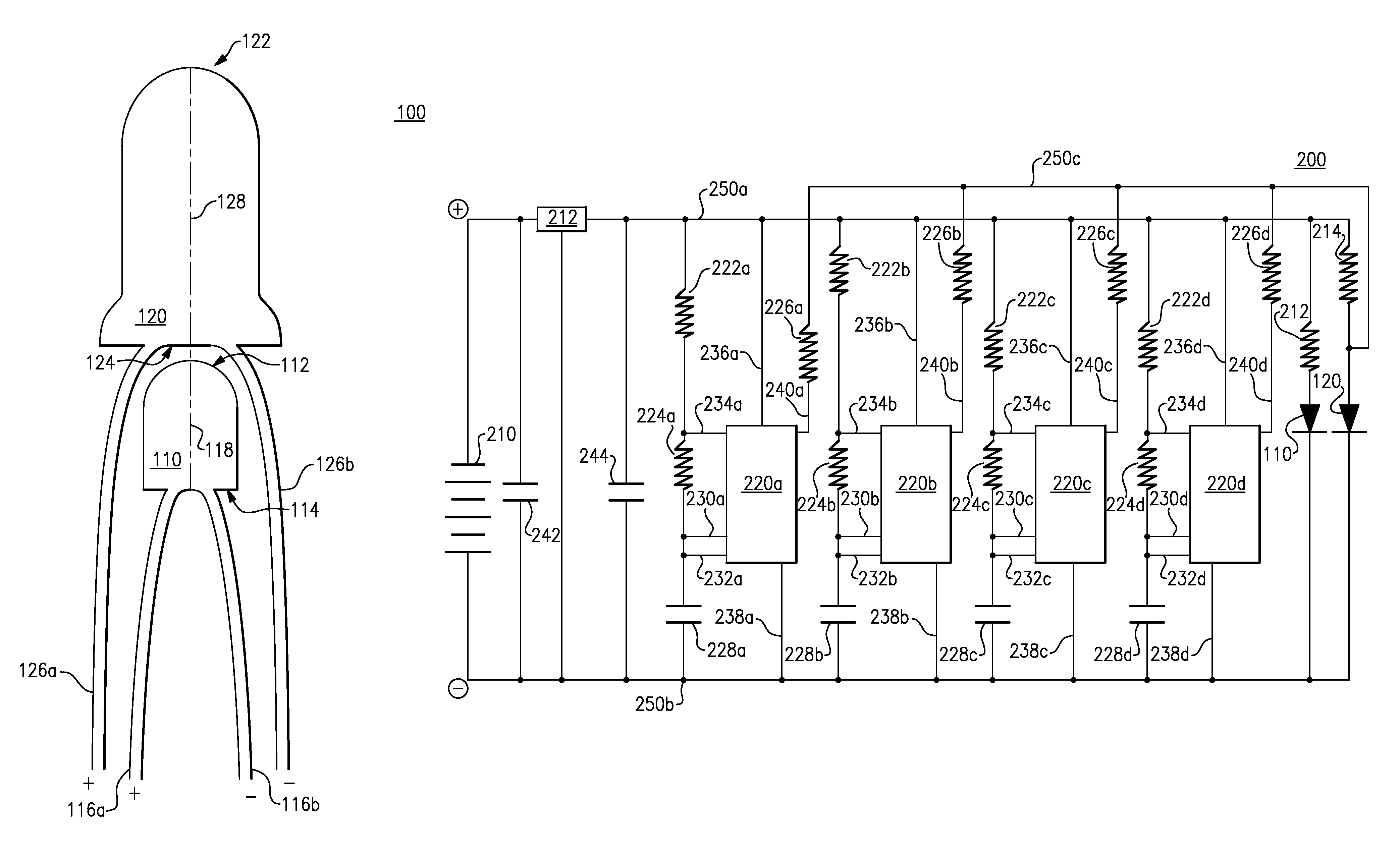
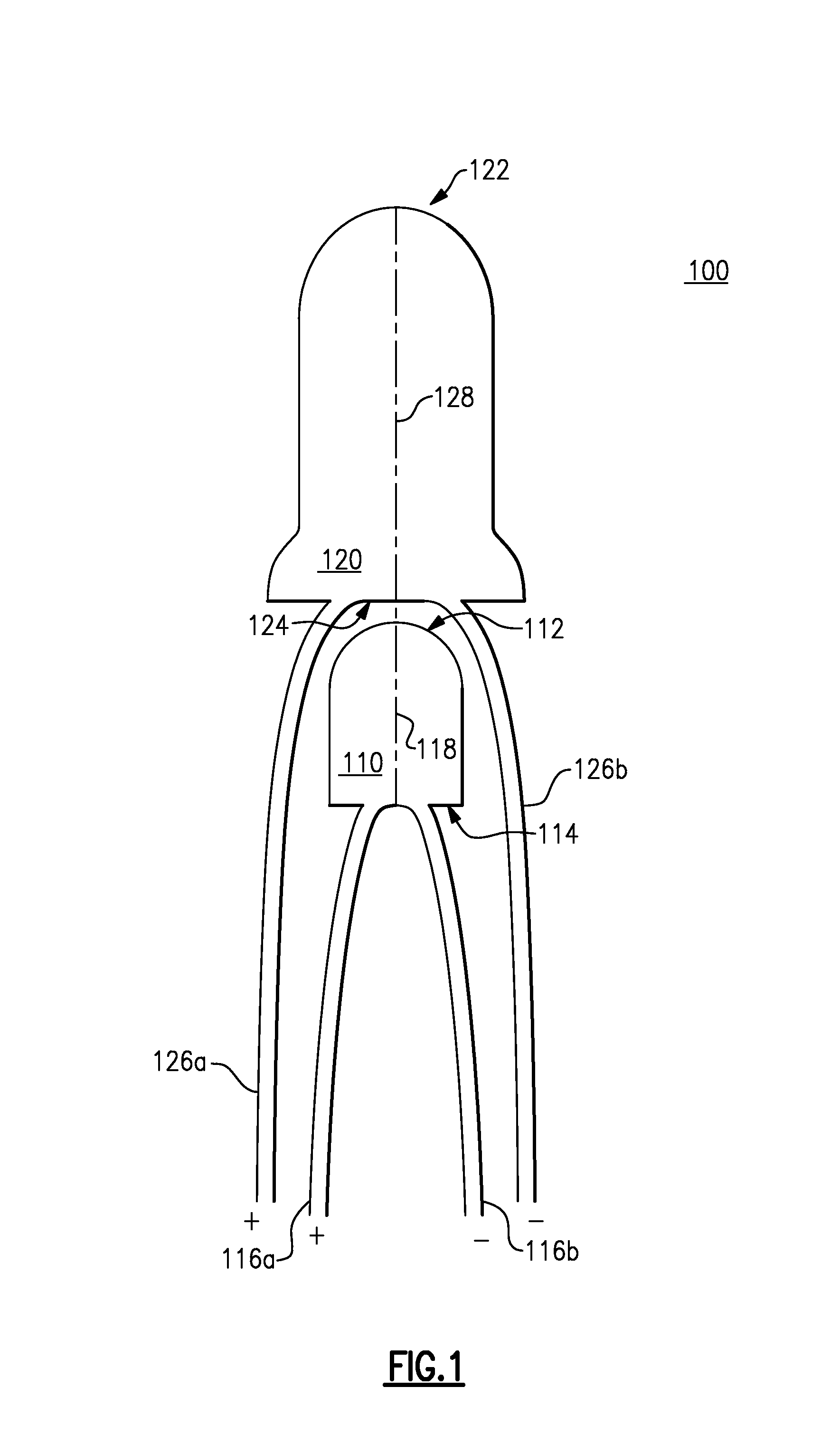
[0012]FIG. 1 illustrates an embodiment 100 of a candle flame simulator including an arrangement of two light emitting diodes (LEDs). As shown, a lower light emitting diode (LED) 110 is disposed below an upper light emitting diode (LED) 120. The lower LED 110 has an upper surface 112 and a lower surface 114 and a longitudinal axis 118 that intersects the upper 112 and lower 114 surfaces. The upper LED 120 has an upper surface 122 and a lower surface 124 and a longitudinal axis 128 that intersects the upper 122 and lower 124 surfaces.

[0013]In other embodiments, another type of light source, can substitute for either the upper 120 or lower 110 light emitting diode. For example, in some embodiments one or more electro-luminescent display devices function as a light source. In some other embodiments, one or more incandescent lights function as a light source.

[0014]As shown, the LEDs 110, 120 are arranged such that the upper surface 112 of the lower LED 110 is located proximate to the low...

embodiment 400

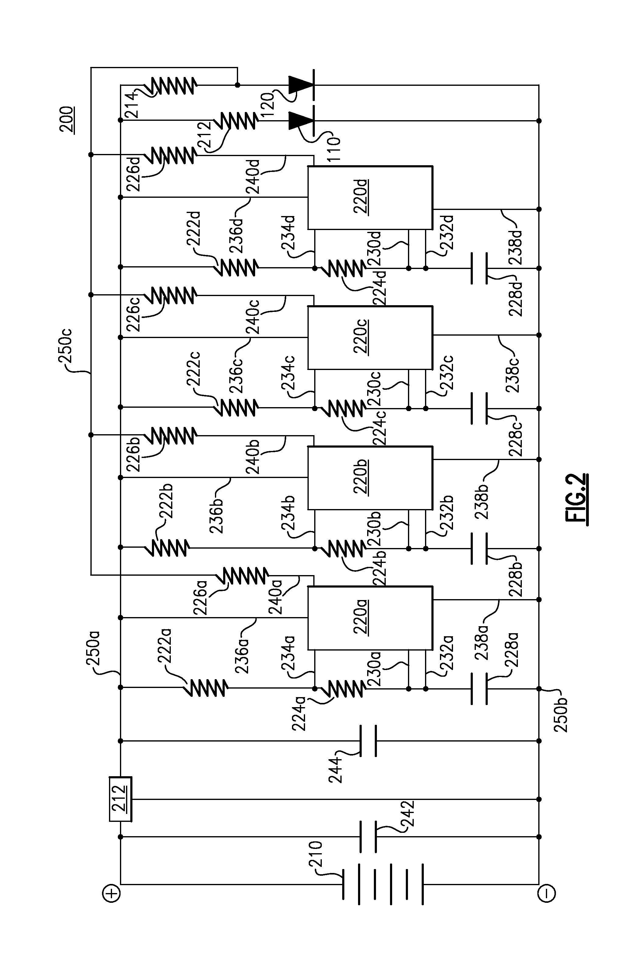
[0054]FIG. 4 illustrates an alternative embodiment 400 of a three volt supplied electronic circuit configured to generate a supplemental intensity signal that includes a superimposition of four individual intensity transition signals. As shown, the electronic circuit 400, also referred to as a circuit 400, includes a (3) volt voltage source supplying positively charged current to the lower LED 110 and to the upper LED 120.

[0055]The flow of current through the lower LED 110 is restricted (limited) by a resistor 412, located downstream of the lower LED 110. This flow of current constitutes a first intensity signal received by the lower LED 110. Also, the flow of current through the upper LED 120 is restricted (limited) by a resistor 414. This flow of current constitutes a base intensity signal received by the upper LED 120.

[0056]The circuit 400 also includes (4) integrated circuit (IC) 555 timer components 220a-220d as shown in FIG. 2. As described in FIG. 2, the timer components 220a...


PUM


Abstract

A method, apparatus and system for electrical simulation of a flame that provides for the projection of light that is a mixture of at least two colors. At least one of the two colors of light is projected over time according to a complex light intensity pattern. The complex light intensity pattern is constructed via an aggregation (superimposition) of a plurality of independent intensity transition signals. Each intensity transition signal represents a separate and varying intensity pattern. The complex light intensity pattern creates a perceptually real and pleasing visual effect upon the human eye, much like that created by the flickering of a real combustion flame and employs other than random or pseudo random intensity patterns.

Description

FIELD OF THE INVENTION[0001]This invention relates generally to an apparatus configured for electrical simulation of a flame, and in particular for simulation of a candle flame.BACKGROUND OF THE INVENTION[0002]The visual appearance of a flame is often pleasing to the human eye in some circumstances. Establishment and maintenance of a real combustion flame can be inconvenient and can create a significant safely risk to people and things located near it. As an alternative, an electrical simulation of a combustion flame can provide much of the visual effect of a combustion flame with less inconvenience and with substantially less risk to the safety of people and things located near it.SUMMARY OF THE INVENTION[0003]The invention provides for a method, apparatus and system for electrical simulation of a flame. In one aspect, the invention provides for the projection of light that is a mixture of at least two colors. At least one of the two colors of light is projected over time according...

Claims


Application Information

Patent Timeline
IPC IPC(8): H05B37/02F21V1/00F21V5/00
CPCF21S10/04H05B33/0842H05B33/0857H05B37/029F21S6/001F21Y2101/02F21Y2115/10H05B45/20H05B45/32H05B47/155
Inventor SMITH, DAVID ERIC
Owner SMITH DAVID ERIC
Learn More