Composite drive shaft with captured end adapters

a technology of end adapters and composite materials, applied in the direction of vertical landing/take-off aircraft, couplings, other domestic articles, etc., can solve the problems of high labor intensity, high cost of mechanical bolting end adapters to the composite material portion, and low torque application, so as to reduce the cost of manufacturing the shaft, reduce the risk of corrosion, and improve the effect of strength

Active Publication Date: 2008-02-26
BELL HELICOPTER TEXTRON INC
View PDF11 Cites 33 Cited by
  • Summary
  • Abstract
  • Description
  • Claims
  • Application Information

AI Technical Summary

Benefits of technology

[0009]The composite drive shaft according to the present invention provides significant benefits and advantages, including: (1) the costs of manufacturing the shaft are lower; (2) the shaft is less susceptible to corrosion; (3) the shaft has greater strength; (4) the shaft is lighter; (5) because the end adapters do not clamp or bite into the composite material, the integrity of the composite material is maintained; (6) because bolts are not necessary, fewer parts are necessary; (7) because bolt holes are not drilled through the composite material and end adapters, crack initiation and propagation is greatly reduced; (8) the shaft can be used in high speed and high torque applications; (9) post-cure cutting and machining of the composite material portion are minimized; and (10) the end adapters can be recovered from defective or damaged assemblies and re-used.

Problems solved by technology

One the of the biggest challenges associated with composite drive shafts is connecting end adapters to the composite material portion.
The first method is currently used in the aircraft industry, the second method is currently used in the automotive industry, and the third method can only be used in low torque applications.
All of these methods have significant disadvantages.
Mechanically bolting the end adapters to the composite material portion is very labor intensive and expensive.
In addition, bolt holes must be drilled through the composite material and end adapter, which can lead to crack initiation and propagation causing potential failure of the shaft.
Clamping or biting into the composite material portion with a serrated end adapter diminishes the integrity of the composite material and reduces the strength of the drive shaft.
As for adhering the end adapters to the composite material portion by adhesive, this method is limited to low torque applications.
Moreover, the adhesive joint may not function properly when undetectable a manufacturing defect exists, or when improper handling occurs during service.

Method used


Image

  • Composite drive shaft with captured end adapters
  • Composite drive shaft with captured end adapters
  • Composite drive shaft with captured end adapters

Examples


Embodiment Construction

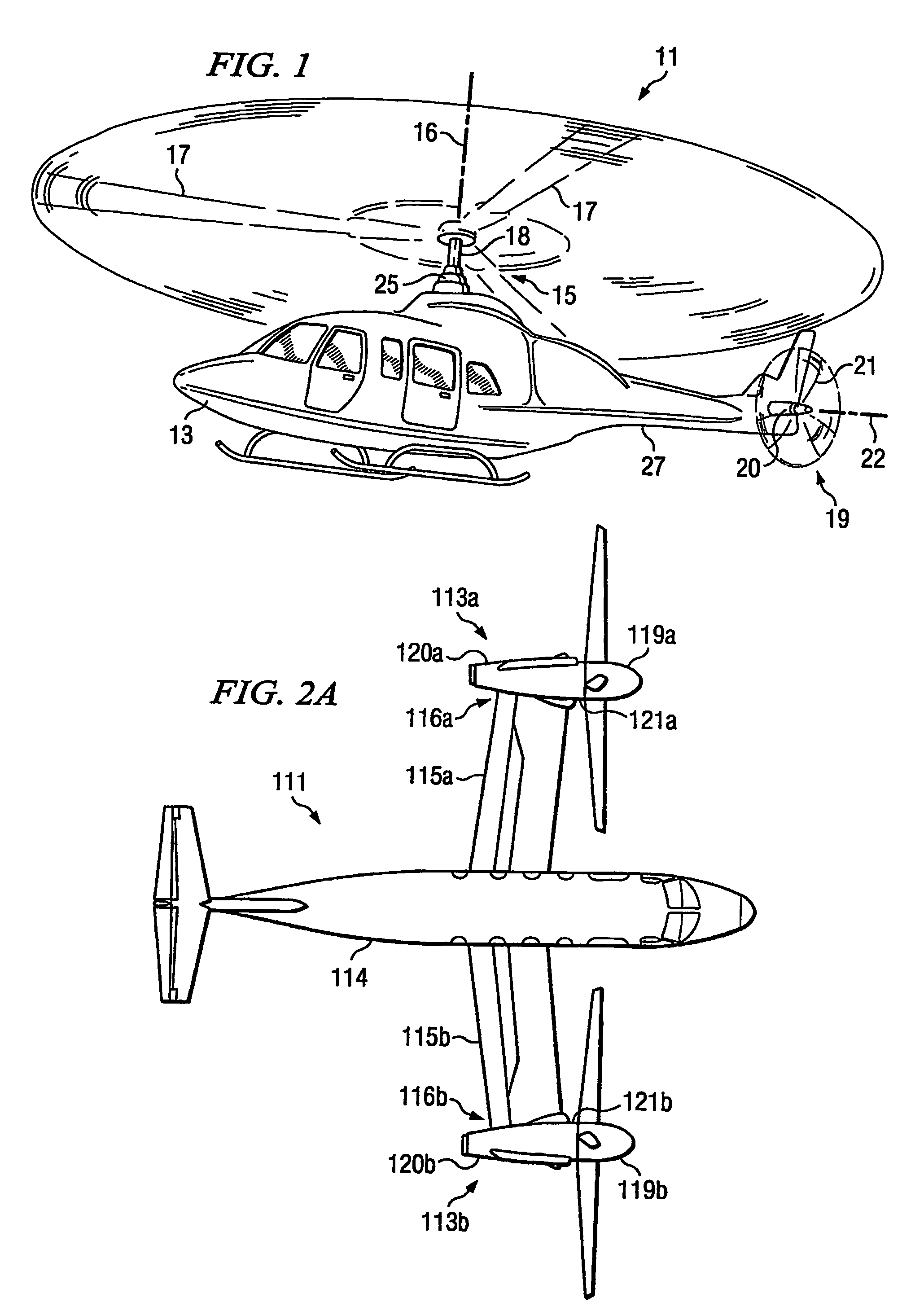
[0022]Referring to FIG. 1 in the drawings, a helicopter 11 having a composite drive shaft with captured end adapters according to the present invention is illustrated. Helicopter 11 has a fuselage 13 and a main rotor assembly 15, including main rotor blades 17 and a main rotor shaft 18. Helicopter 11 has a tail rotor assembly 19, including tail rotor blades 21 and a tail rotor shaft 20. Main rotor blades 17 generally rotate about a longitudinal axis 16 of main rotor shaft 18. Tail rotor blades 21 generally rotate about a longitudinal axis 22 of tail rotor shaft 20. Main rotor blades 17 and tail rotor blades 21 are driven by a drive means 25 carried by fuselage 13. Torque is transmitted from drive means 25 to tail rotor assembly 19 through at least one composite drive shaft having captured end adapters that is disposed within a tail boom 27.

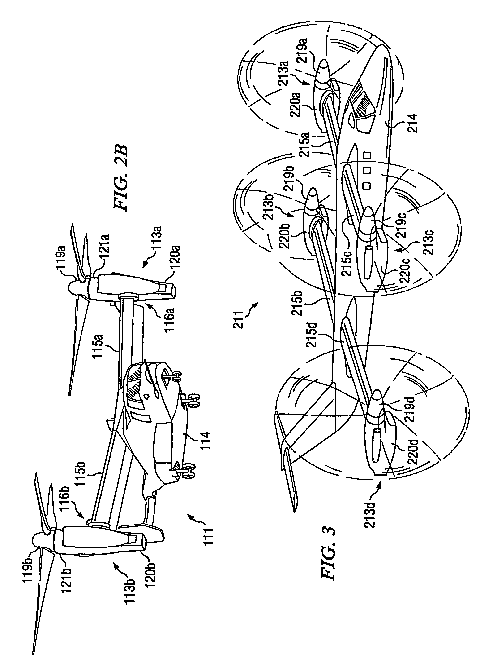
[0023]The present invention may also be utilized on other types of rotary wing aircraft. Referring now to FIGS. 2A and 2B in the drawings, a tilt...


PUM

PropertyMeasurementUnit
torqueaaaaaaaaaa
metallicaaaaaaaaaa
cross-sectional areaaaaaaaaaaa

Abstract

A composite drive shaft in which the end adapters are captured in the composite material portion during the process of manufacturing of the composite drive shaft assembly is disclosed. The end adapters include lugs that protrude outward longitudinally to transmit torque, tensile, and compressive forces, and bending moments to the composite material portion and vice versa. To increase the load carrying capacity for axial force and bending moment, the end adapters may have at least one recessed circumferential groove. Before the manufacturing process, one or more bonding agents may be applied onto the interface of the end adapter to enhance the performance of engagement between the end adapters and the composite material portion. The composite material portion and end adapters are co-cured to produce a final drive shaft that requires no additional work for assembly.

Description

TECHNICAL FIELD[0001]The present invention relates to composite drive shafts.DESCRIPTION OF THE PRIOR ART[0002]Composite drive shafts have been in use for many years. Because they are lighter than metallic drive shafts, they are particularly useful in industries where weight is a significant concern, such as in the aircraft industry and the automotive industry. Composite drive shafts usually consist of a composite material portion with a metallic end adapter connected to each end of the portion.[0003]One the of the biggest challenges associated with composite drive shafts is connecting end adapters to the composite material portion. There are basically three ways to connect the end adapters to the composite material portion: (1) by mechanically bolting the end adapters to the composite material portion; (2) by clamping or biting into the composite material with a serrated end adapter; and (3) by adhering the end adapter to the composite material portion. The first method is currentl...

Claims


Application Information

Patent Timeline
Patent Type & Authority Patents(United States)
IPC IPC(8): F16C3/02B29C70/46B29C70/48B29C70/86B64C29/00B64D35/00B65H81/00F16D1/064
CPCB29C70/462B29C70/48B29C70/86B64C29/0033B64D35/00F16C3/026F16D1/064B29L2031/75F16D2250/00F16C2326/43
Inventor LIN, SHERMAN S.POSTER, SCOTT D.
Owner BELL HELICOPTER TEXTRON INC
Why Eureka
Try Eureka