Solar energy concentrator device for spacecraft and a solar generator panel

a solar generator and solar energy technology, applied in the direction of electric vehicles, machines/engines, propulsion parts, etc., can solve the problems of reducing the ratio by which the panel is filled with cells, the flow of solar generator output current between the cells, and the loss of sections of solar panels. achieve the effect of high reflectivity in the visible spectrum

Inactive Publication Date: 2008-03-04
THALES SA
View PDF12 Cites 32 Cited by
  • Summary
  • Abstract
  • Description
  • Claims
  • Application Information

AI Technical Summary

Benefits of technology

[0028]In one embodiment of the invention, the external wall of the reflector is covered with a coating adapted to reflect visible light, for example by depositing an aluminum film, and its internal wall is covered with a high-emissivity coating, for example black paint.

Problems solved by technology

However, anomalies corresponding to loss of sections of solar panels have been observed with this type of array.
Further analyses and tests have shown that an electrostatic discharge between a solar cell of a panel and its cover glass can cause a short circuit between the

Method used


Image

  • Solar energy concentrator device for spacecraft and a solar generator panel
  • Solar energy concentrator device for spacecraft and a solar generator panel
  • Solar energy concentrator device for spacecraft and a solar generator panel

Examples


Embodiment Construction

[0047]Components with exactly the same function are identified by the same reference numbers in all the figures.

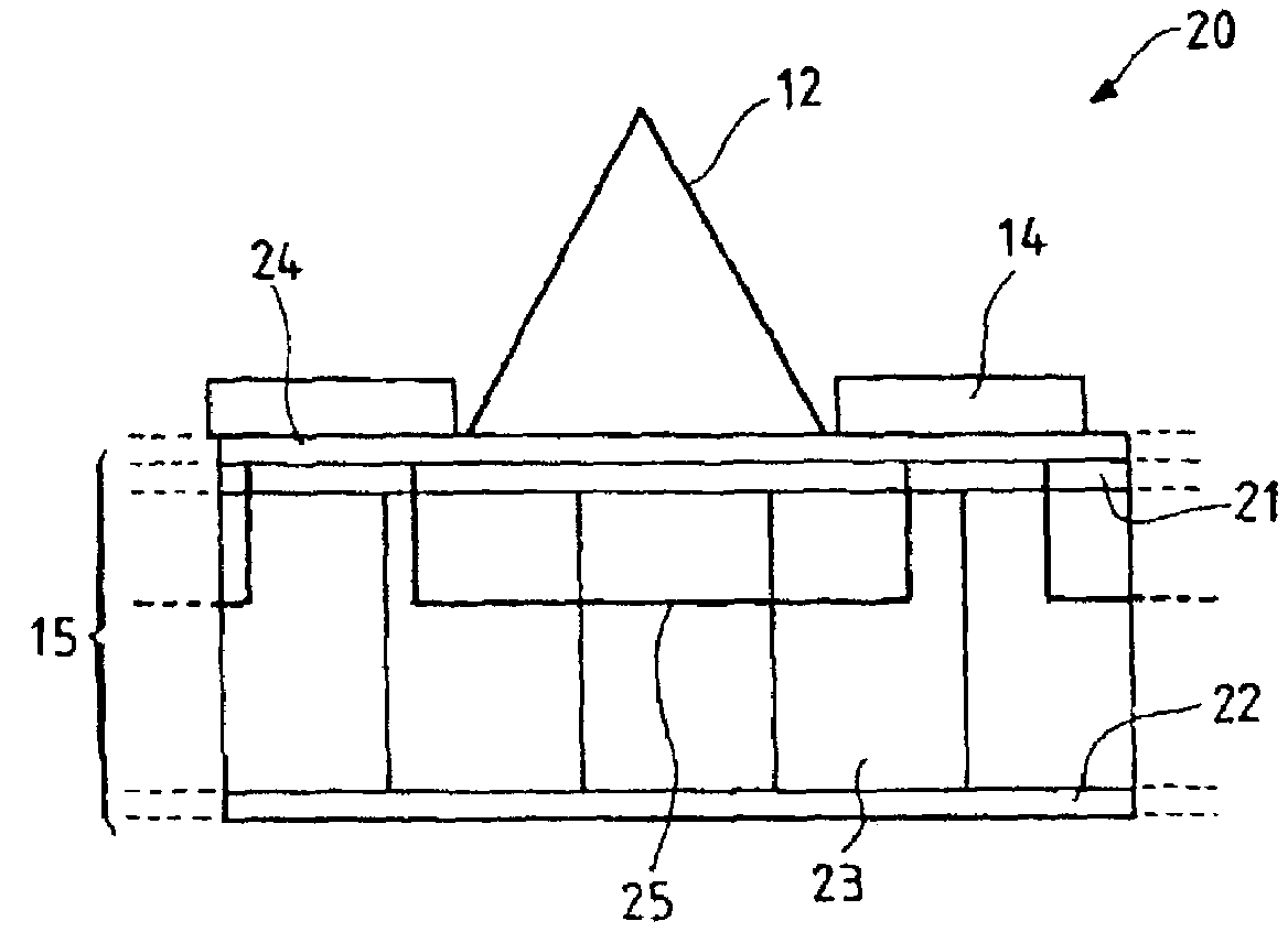
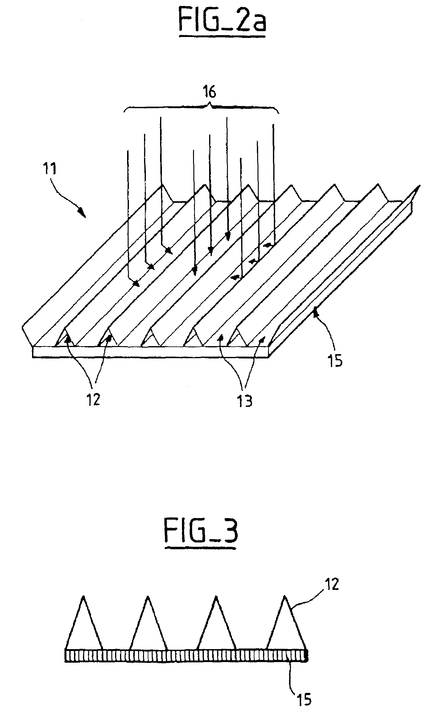
[0048]FIG. 2a is a diagrammatic perspective view of a solar generator panel 11.

[0049]The panel 11 has, on its face intended to be oriented toward the light source, an alternating succession of reflectors 12 and strings 13 of solar cells 14. Note that in this embodiment the reflectors have a sawtooth configuration. Any other reflector shape can of course be envisaged, whether of the parabolic or other type. The reflectors and the cells are supported by a support panel 15.

[0050]FIGS. 2a and 2b show, in the form of a plurality of arrows, a solar flux 16, some beams 27 of which illuminate the cell 14 directly, while other beams 26 impinge on the cell after reflection at a reflector.

[0051]Note further in FIGS. 2a and 6 (described below) that the cells and reflectors are arranged across the width of the panels, to minimize any penalty in respect of the power balance should an an...


PUM


Abstract

A device is disclosed for reducing the risk of primary and secondary electrostatic discharges occurring in particular in the solar generators of spacecraft. A solar energy concentrator device for spacecraft includes a reflector for reflecting solar radiation onto a photovoltaic cell for converting solar energy into electrical energy and a heat transfer arrangement for transporting to a cold area heat energy stored by the cell following reception of solar radiation. One particular application of the device is to solar panels for satellites.

Description

CROSS-REFERENCE TO RELATED APPLICATIONS[0001]This application is based on French Patent Application No. 02 00 127 filed Jan. 7, 2002, the disclosure of which is hereby incorporated by reference thereto in its entirety, and the priority of which is hereby claimed under 35 U.S.C. §119.BACKGROUND OF THE INVENTION[0002]1. Field of the Invention[0003]The present invention relates generally to arrays of solar energy concentrators, in particular for space applications. It relates more particularly to an energy concentrator device employing solar cells.[0004]2. Description of the Prior Art[0005]The solar generator panels carried on a spacecraft such as a geosynchronous satellite generally comprise:[0006]panels supporting an array of identical or different photovoltaic cells for converting solar energy into electrical energy, and[0007]an array of identical or different solar cells forming strings of cells that are electrically connected and cover the surface of the support panel.[0008]Solar ...

Claims


Application Information

Patent Timeline
IPC IPC(8): H01L31/052B64G1/44F24J2/18F24S23/79H01L31/042H01L31/054
CPCH01L31/052H01L31/0547Y10S136/292Y02E10/52F28D2015/0225H01L31/0521
Inventor TUR, MYRIAMDARGENT, THIERRYBROSSE, SYLVIE
Owner THALES SA
Why Eureka
Try Eureka