
MRI/MRS gradient coil with integrated cooling circuits

a cooling circuit and gradient coil technology, applied in the field of magnetic resonance imaging and magnetic resonance spectroscopy devices, can solve the problems of reducing the efficiency increasing the heat generation of the gradient coil, and creating significant discomfort for the patient being examined, so as to reduce the heat in the patient's examination spa

Active Publication Date: 2008-03-04
GENERAL ELECTRIC CO
View PDF18 Cites 10 Cited by
  • Summary
  • Abstract
  • Description
  • Claims
  • Application Information

AI Technical Summary

Benefits of technology

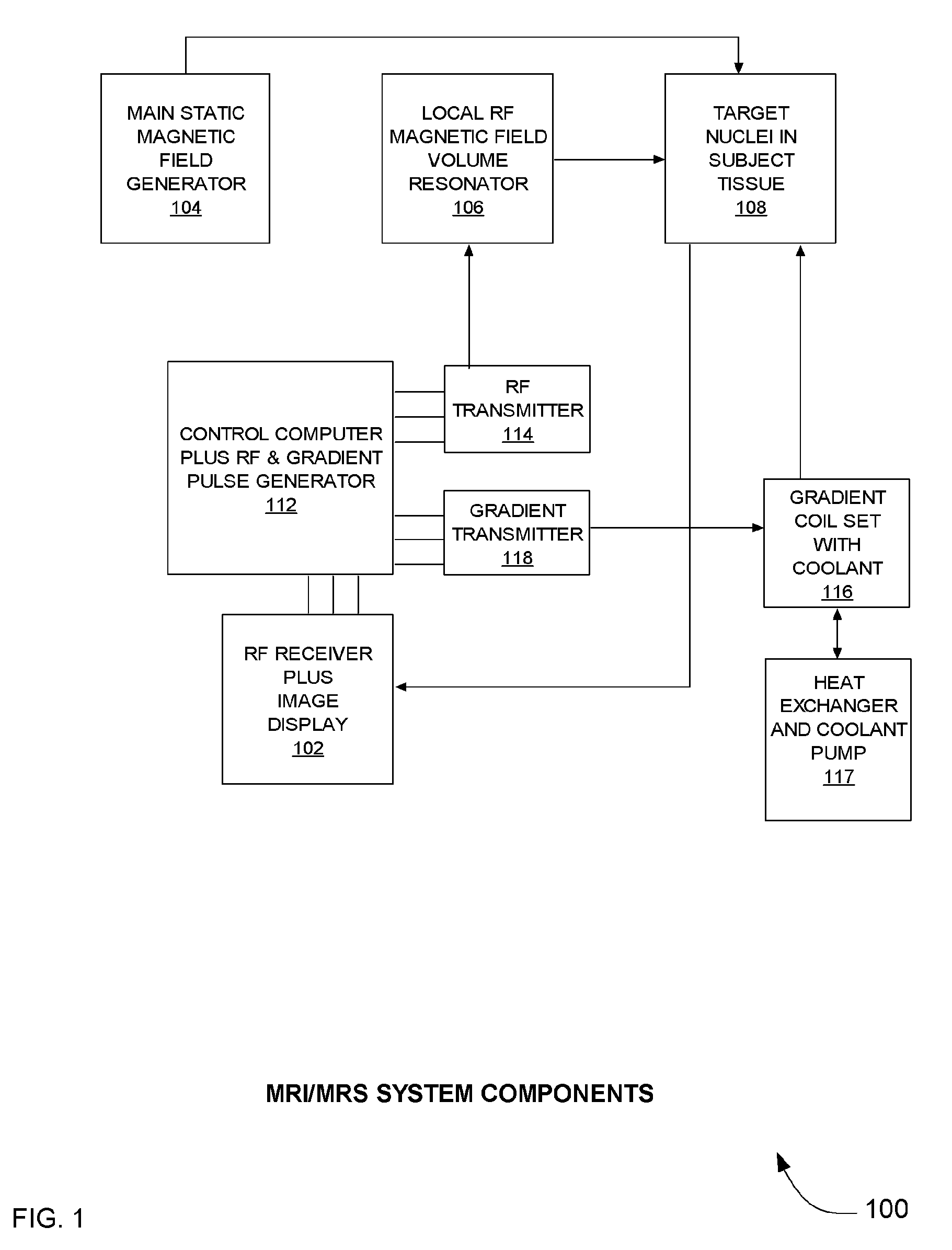
[0010]In one aspect, an MRI / MRS system for medical examination includes a component which reduces the heat in the patient's examination space without compromising the efficiency of the gradient fields used to alter the main magnetic fields.
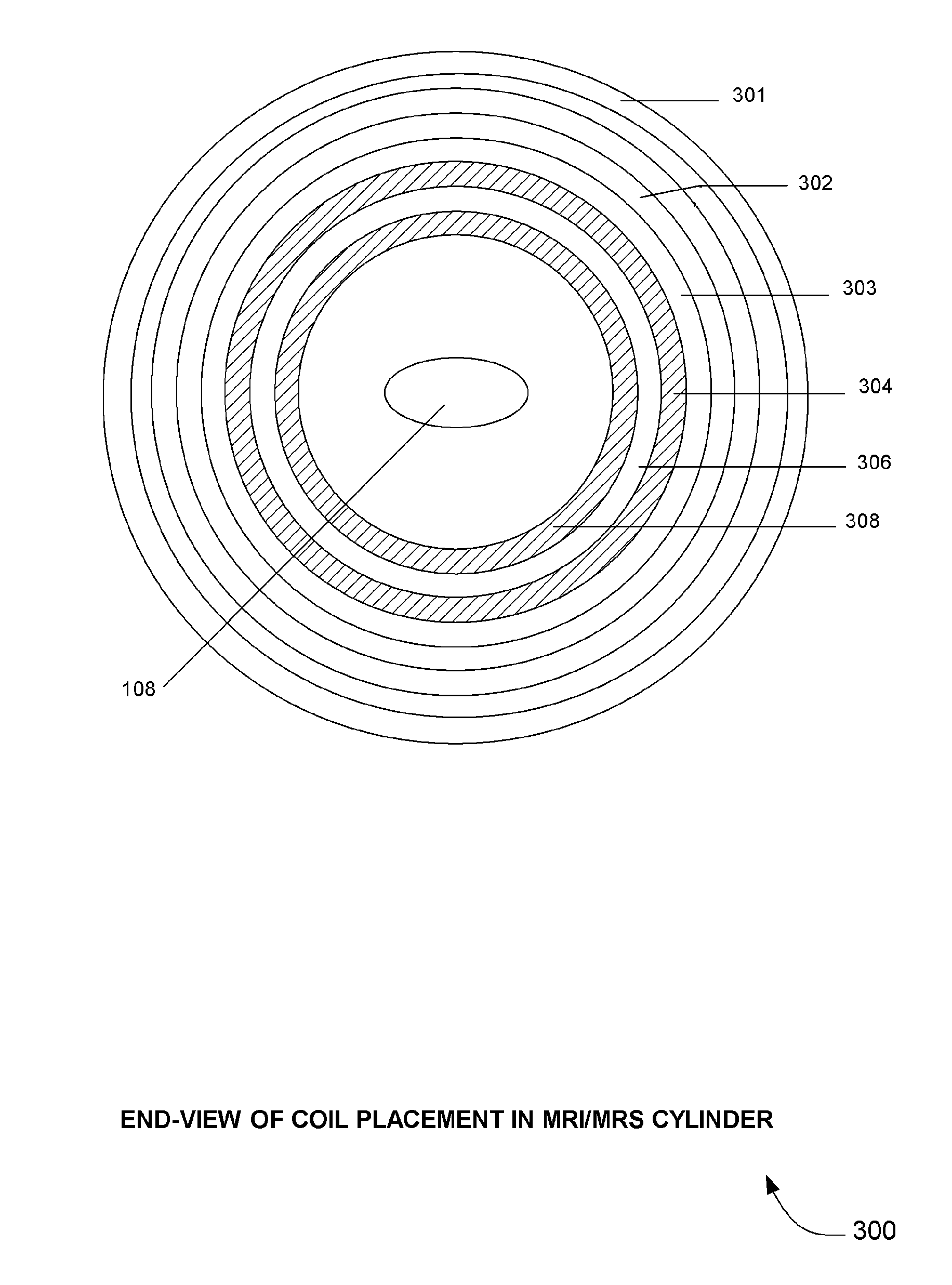
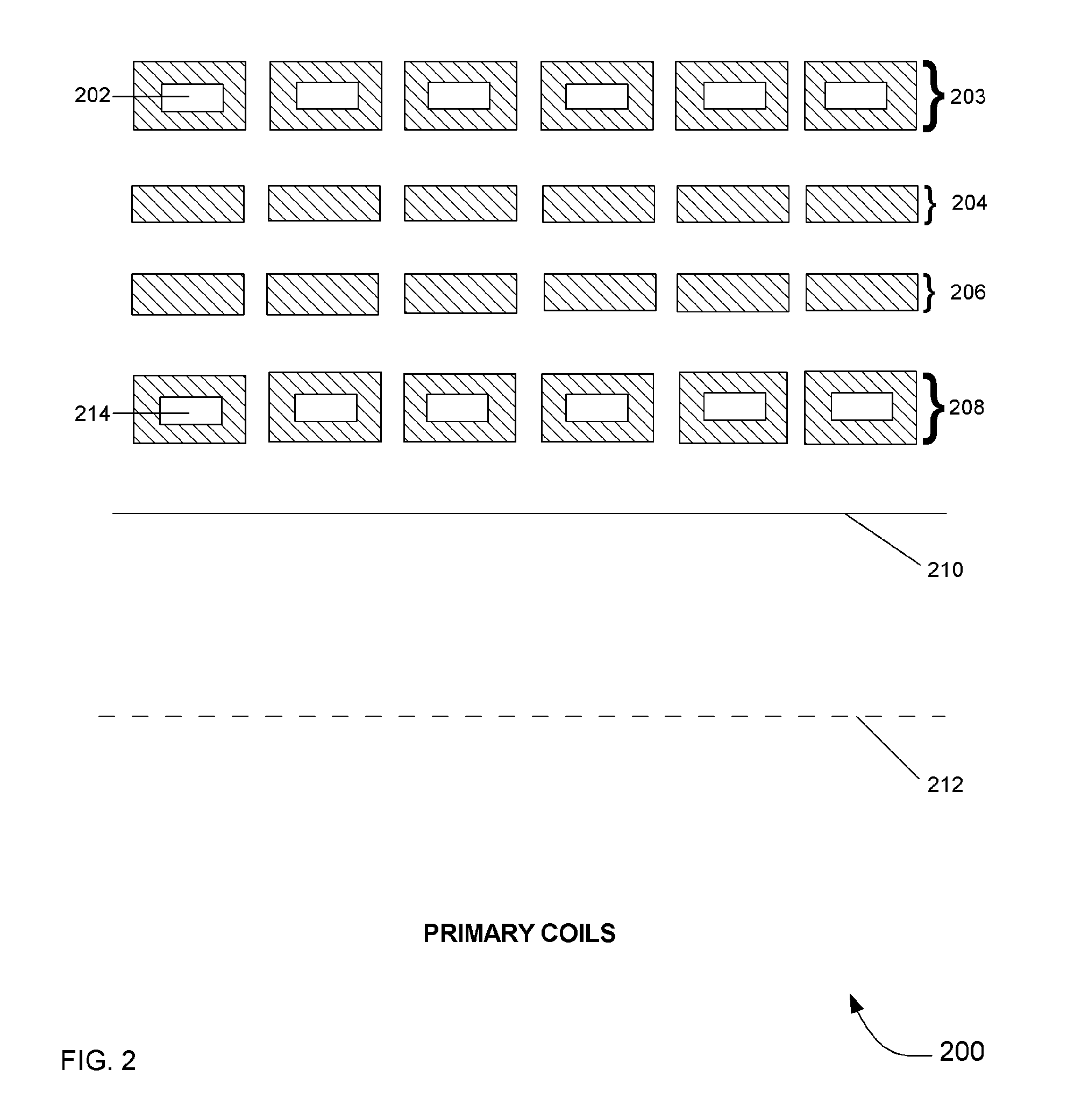
[0011]In another aspect, the component of the MRI / MRS system that reduces the heat experienced in the enclosed examination space from the power used to create the system's electromagnetic fields, is a split current-carrying coil of two connected layers containing coolant in one layer.
[0013]In another aspect, the cooling effect of the split current-carrying coil of two connected layers containing coolant in one layer is altered by the number of turns in each of the two connected layers.

Problems solved by technology

Unlike the main magnetic field, coils used to create the gradient fields are not super-cooled, and, as a result, sometimes generate enough heat to create significant discomfort for the patient being examined.
Any effort to reduce patient discomfort by placing cooling units within the walls of the cylinder between the patient and the gradient coils increases the distance between the patient and the coils that create the gradient fields, which reduces the efficiency of the gradient coil.
A greater distance means a gradient coil will have higher resistance and inductance for a given coil gain (gradient strength per unit current) and for a given gradient field linearity, which results in higher heat generation and lower coil switching speed.
Increasing the current in the coils to improve the gradient strength at the greater distance not only increases power consumption raising the cost of operation of the MRI / MRS device, but defeats the purpose of the cooling units by increasing the heat generated by the coil.

Method used


Image

  • MRI/MRS gradient coil with integrated cooling circuits
  • MRI/MRS gradient coil with integrated cooling circuits
  • MRI/MRS gradient coil with integrated cooling circuits

Examples


Embodiment Construction

[0021]In the following detailed description, reference is made to the accompanying drawings that form a part hereof, and in which is shown by way of illustration specific embodiments which may be practiced. These embodiments are described in sufficient detail to enable those skilled in the art to practice the embodiments, and it is to be understood that other embodiments may be utilized and that logical, mechanical, electrical and other changes may be made without departing from the scope of the embodiments. The following detailed description is, therefore, not to be taken in a limiting sense.

[0022]The detailed description is divided into five sections. In the first section, a system level overview is described. In the second section, apparatus of embodiments are described. In the third section, embodiments of methods are described. In the fourth section, a hardware and operating environment is described. Finally, in the fifth section, a conclusion of the detailed description is pro...


PUM


Abstract

Systems, methods and apparatus are provided through which heat produced in the patient examination space by the power used to create electromagnetic fields in an MRI / MRS system is significantly reduced by coolant carried by one of two split connected concentric coil layers of one of two of the primary gradient coils used to alter the main magnetic field. The coil carrying the coolant is made of copper tubing. The second primary gradient coil is placed between the layers of the split primary gradient coil. Adjusting the number of turns in each layer of the split primary gradient coil adjusts the heat generated. The inductances and resistances of the two primary gradient coils are balanced by adjusting the gain of the coils.

Description

FIELD OF THE INVENTION[0001]This invention relates generally to Magnetic Resonance Imaging and Magnetic Resonance Spectroscopy devices, and more particularly to cooling systems, methods and apparatus for the gradient coils used in Magnetic Resonance Imaging and Magnetic Resonance Spectroscopy medical devices.BACKGROUND OF THE INVENTION[0002]The value of Magnetic Resonance Imaging (MRI) devices for medical use was recognized almost immediately after they first appeared in the 1970s. Because they appear both to do no harm to the human body, and to create better images of the body's interior than the best X-ray technology, they have gained widespread use for diagnosis, pre-operative examination and even for assistance during surgical procedures. While MRI provides information on size and location of pathological abnormalities such as tumors, a variation of magnetic resonance technology called Magnetic Resonance Spectroscopy (MRS)—which identifies various biochemicals and their concentr...

Claims


Application Information

Patent Timeline
Patent Type & Authority Patents(United States)
IPC IPC(8): G01V3/00
CPCG01R33/3856
Inventor LIU, QIN
Owner GENERAL ELECTRIC CO
Learn More