Parabolic trough solar collector for fluid heating and photovoltaic cells

a solar collector and fluid heating technology, applied in the safety of solar heat collectors, lighting and heating apparatus, furnaces, etc., can solve the problems of high cost of maintenance, low efficiency of solar power generating plants, and low cost of maintenance, so as to reduce weight and cost, the support of fixed conduits and suspended reflector panels is simplified.

Inactive Publication Date: 2008-03-18
NIEDERMEYER WILLIAM P
View PDF12 Cites 34 Cited by
  • Summary
  • Abstract
  • Description
  • Claims
  • Application Information

AI Technical Summary

Benefits of technology

[0007]Generally, all solar collector power systems perform the same functions and require the same basic components including a parabolic reflector to focus solar rays on a heat absorbing conduit. Other components added to increase conversion efficiency include means to continuously pivot the reflector as the sun moves from east to west and the vacuumzed glass tube surrounding the heat absorbing pipe to reduce emissive heat loss to ambient air.
[0008]Because of the gradient from ambient temperature to maximum, the difference in expansion of the glass tube and absorber pipe in current SEG designs requires an “expansion bellows” between sections of conduit and are prone to leakage and loss of vacuum. Components of the invention lower emission heat loss and vacuum leakage.
[0010]The instant collector system counters the difference in expansion of pipe and enclosing glass by eliminating bellows of current designs and using a plurality of conduit insulators comprised of two concentric tubes sealed at the ends to define a vacuum space. Insulators are separated by resilient compression springs to allow for insulator expansion independent from expansion of the pipe. The insulator has central openings and surrounds the pipe. Supports for the fixed conduit and a suspended reflector panel are simplified because of weight reduction.
[0012]The primary objective of the instant collector system is cost reduction by using low cost corrugated board processed on existing machinery for high speed production of parabolic elements and using a cutting system to make parabolic shapes per U.S. Pat. Nos. 4,190,037 and 4,416,263 which states that flexible members on the top edge of support segments can be either U or L shaped, and cutouts between adjacent tabs can be eliminated if the bending modulus of the flexible piece so allows. FIGS. 2, 3, and 4 of U.S. Pat. No. 4,416,263 show typical flexible pieces.
[0014]Using abundantly available and low cost corrugated board stock processed at high speed to form the parabolic shape of transverse segments in a unitary panel, a simplified collector support and pivot system in and vacuum insulators manufactured in large quantities like florescent lights, the instant disclosure offers potential for low cost collection of solar energy for supplementary electric power generation and, with commercially available devices for electrolysis to produce hydrogen from a renewable non-fossil fuel solar energy source for use in fuel cells.

Problems solved by technology

Current designs have inherent cost and maintenance problems which together with the cyclic nature of the sun (including cloudy days) prevents solar power generating plants from producing cost effective power available around the clock.
Aside from cost and operating differences, the combined cycle plant still had CO2 emissions and is subject to fossil fuel price fluctuations or supply disruptions.
Because of the gradient from ambient temperature to maximum, the difference in expansion of the glass tube and absorber pipe in current SEG designs requires an “expansion bellows” between sections of conduit and are prone to leakage and loss of vacuum.

Method used


Image

  • Parabolic trough solar collector for fluid heating and photovoltaic cells
  • Parabolic trough solar collector for fluid heating and photovoltaic cells
  • Parabolic trough solar collector for fluid heating and photovoltaic cells

Examples


Embodiment Construction

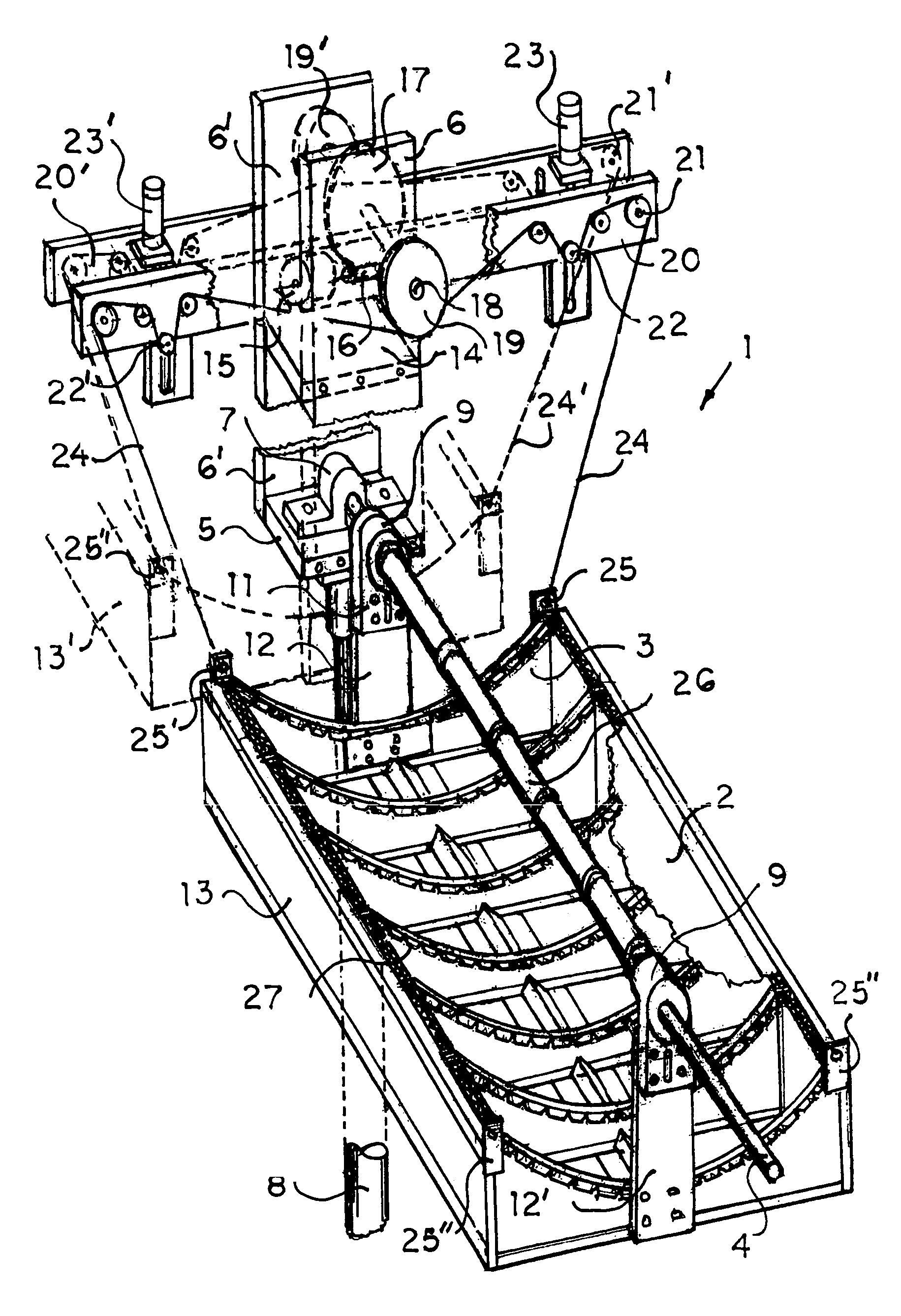
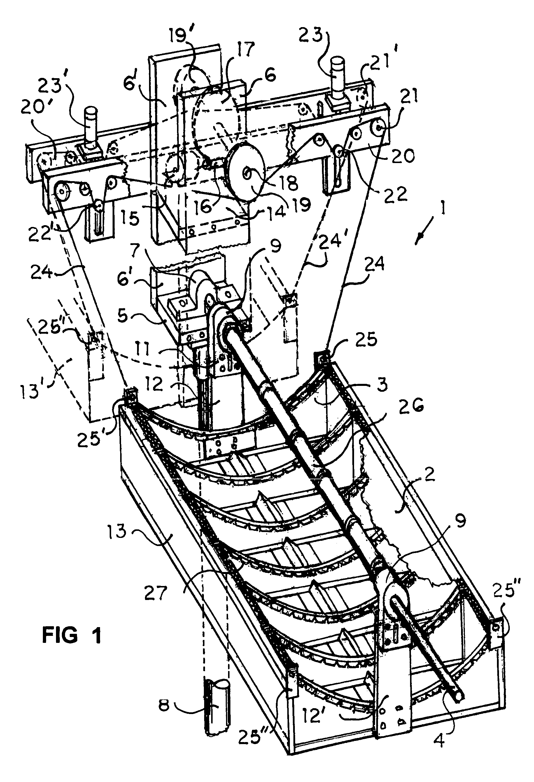
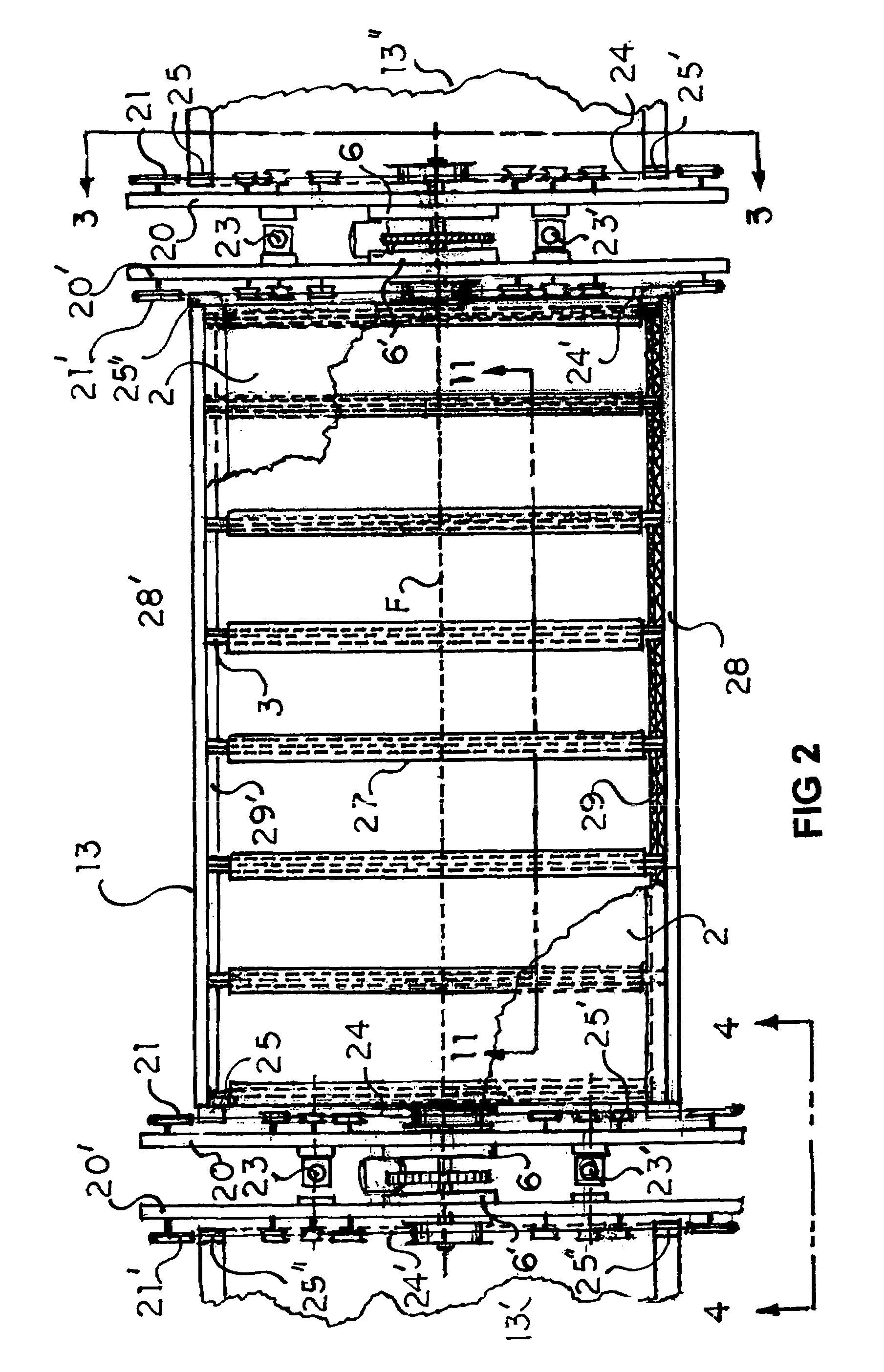
[0036]In FIG. 1, the parabolic trough concentrating collector 1 reflects solar rays from reflector surface 2 (portions cutaway) supported by a plurality of parabolic shaped transversely aligned corrugated board segments 3 with flexible strips 27 superposed and attached to side surfaces (as shown in FIGS. 1, 5, 6).

[0037]Reflected rays are directed to a focal line F co-incident with the centerline of conduit 4 which is secured to cross member 5 of vertically extended support 6 by clamp 7.

[0038]In FIG. 1, support extensions 6, 6′ and cross supports 5, 14 are attached to stationary post 8 and are fixed. Housing 9 with inside bushings 10 include a downwardly extending portion 11 for connection to and support of reflector support arms 12, 12′ which are attached to both ends of unitary reflector 13. The reflector 13, support arms 12, 12′, housing extensions 11, 11′ and housings 9, 9′ pivot from conduit 4.

[0039]In FIG. 1, the upper support extensions 6, 6′ include cross member 14 to support...


PUM


Abstract

A solar concentrating collector includes corrugated board parabolic support segments with flexible strips and side tabs over the cut edge to support a laminate with reflective coated film. The reflector assembly has supporting arms and pivots about a heat absorbing conduit secured to vertical extensions of adjacent stationary posts. Selected external surfaces are weatherproofed. The conduit includes vacuum insulators and means to isolate conduit from insulator expansion. Upper arms support pulleys and cable take-ups for continuous collector position changes. Cross members of the extended post secure the fixed conduit, and at a higher level, a programmable drive to rotate two cable capstans for cables that pivot two adjacent reflector assemblies. Other embodiments include triangular or square fluid conduits with planar surfaces for photovoltaic cells and a modified reflective surface to disperse solar rays into a band of reflected sunlight directed to photocell areas.

Description

BACKGROUND AND SUMMARY OF THE INVENTION[0001]The use of linear parabolic reflector troughs for concentrating solar rays on a heat collector pipe is well known. Prior collector systems for heating fluids to generate power depend from and use many of the same components as systems going back 40 or more years.[0002]Several current “state of the art” solar energy generating plants (SEGS) ranging from 30 to 320 megawatts are operating in the Mojave desert of California. The collectors include spaced parabolic truss supports extending transversely from about 6 to 18 ft wide. Collector systems heat fluids from 560 degrees to over 700 degrees F., and all use trusses extending outward from a pivoting central structure or tube, to support cast linear parabolic shaped mirrors to form the trough.[0003]Current parabolic mirror reflectors and trusses together with the attached absorber conduit are pivoted about a central structure or tube using hydraulic actuators and speed reduction gear boxes.[...

Claims


Application Information

Patent Timeline
Patent Type & Authority Patents(United States)
IPC IPC(8): F24J2/52F24J2/38F24S50/20
CPCF24J2/055F24J2/14F24J2/38F24J2/541F24J2/523F24J2002/5458F24J2002/5468Y02E10/44Y02E10/45Y02E10/47F24J2/4636Y10S126/906Y02E10/52H01L31/0547F24S40/80F24S2023/874F24S23/74F24S50/20F24S2030/133F24S30/425F24S25/10F24S10/45F24S2030/136Y02E10/40
Inventor NIEDERMEYER, WILLIAM PAUL
Owner NIEDERMEYER WILLIAM P
Why Eureka
Try Eureka