Method and apparatus for production of a cast component

a technology of casting components and casting components, applied in the direction of additive manufacturing with solids and fluids, liquid transferring devices, crystal growth processes, etc., can solve the problem of limiting the allowable temperature of working fluids, and achieve the effect of reducing heat transfer

Inactive Publication Date: 2008-03-18
ROLLS ROYCE CORP
View PDF54 Cites 27 Cited by
  • Summary
  • Abstract
  • Description
  • Claims
  • Application Information

AI Technical Summary

Benefits of technology

[0015]Yet another form of the present invention contemplates a method, comprising: providing a mold having an internal cavity adapted for the receipt of molten metal therein, the cavity has a top portion, bottom portion and side portion, insulating the ceramic shell to minimize heat transfer through said side portion; placing the mold within an environmental control chamber; filling the cavity with molten metal to form a casting defined by the cavity; and directionally solidifying the molten metal within the mold by withdrawing energy from one end of the casting.

Problems solved by technology

One factor recognized by gas turbine engine designers as limiting the allowable temperature of the working fluid is the capability of the engine components to not degrade when exposed to the high temperature working fluid.
The airfoils, such as blades and vanes, within the engine are among the components exposed to significant thermal and kinetic loading during engine operation.

Method used


Image

  • Method and apparatus for production of a cast component
  • Method and apparatus for production of a cast component
  • Method and apparatus for production of a cast component

Examples


Embodiment Construction

[0084]For the purposes of promoting an understanding of the principles of the invention, reference will now be made to the embodiment illustrated in the drawings and specific language will be used to describe the same. It will nevertheless be understood that no limitation of the scope of the invention is thereby intended, such alterations and further modifications in the illustrated device, and such further applications of the principles of the invention as illustrated therein being contemplated as would normally occur to one skilled in the art to which the invention relates.

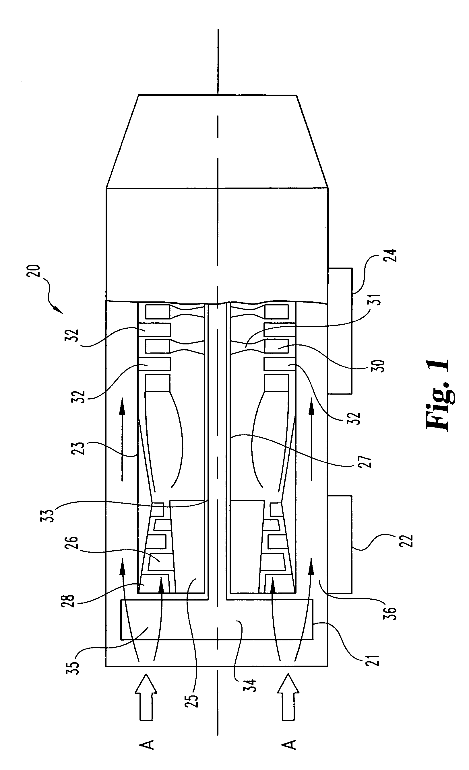
[0085]Referring to FIG. 1, there is illustrated a gas turbine engine 20 which includes a fan section 21, a compressor section 22, a combustor section 23, and a turbine section 24 that are integrated together to produce an aircraft flight propulsion engine. This type of gas turbine engine is generally referred to as a turbo-fan. One alternate form of a gas turbine engine includes a compressor, a combustor, and a ...


PUM

PropertyMeasurementUnit
thicknessaaaaaaaaaa
widthaaaaaaaaaa
depthsaaaaaaaaaa

Abstract

A system for producing cast components from molten metal. One form of the present invention includes a system for the precision pouring of molten metal within a casting mold. The precision pouring system is driven by a pressure differential.

Description

CROSS REFERENCE TO RELATED APPLICATIONS[0001]The present application is a divisional of U.S. patent application Ser. No. 10 / 462,168 filed Jun. 16, 2003 now abandoned which is a continuation of U.S. patent application Ser. No. 09 / 444,155 filed Nov. 20, 1999 now abandoned. U.S. patent application Ser. No. 09 / 444,155 claims, the benefit of a U.S. provisional application having a Ser. No. 60 / 109,298 that was filed on Nov. 20, 1998. Application Ser. No. 09 / 444,155 is a continuation-in-part of Ser. No. 09 / 322,863 that was filed on May 28, 1999 now abandoned. Each of the above listed applications is incorporated herein by reference.BACKGROUND OF THE INVENTION[0002]The present invention relates generally to a method and apparatus for the production of a cast component. More particularly, in one embodiment of the present invention, a single cast single crystal structure is formed by the directional solidification of a superalloy within a precision casting mold containing a starter seed. Alth...

Claims


Application Information

Patent Timeline
Patent Type & Authority Patents(United States)
IPC IPC(8): B22D37/00B29C67/00C30B11/00C30B11/14G03F7/00G03F7/004
CPCG03F7/0047B29C67/0092C30B11/002B29C67/0081C30B11/14G03F7/0037C30B11/00B22D47/00C30B29/52Y10T117/10Y10T117/1016Y10S117/90B33Y80/00B29C64/165B29C64/40
Inventor FRASIER, DONALD J.SCHLIENGER, M. ERIC
Owner ROLLS ROYCE CORP
Why Eureka
Try Eureka