Drill

a power tool and portable technology, applied in the field of powered drilling apparatus, can solve the problems of inability to be used in limited quarters, large and heavy motors, and prior art devices that are not adaptable to other manufacturing situations

Active Publication Date: 2008-03-18
WEST COAST INDS
View PDF8 Cites 10 Cited by
  • Summary
  • Abstract
  • Description
  • Claims
  • Application Information

AI Technical Summary

Benefits of technology

[0029]With the hydraulic valve in it first position, pressurized hydraulic fluid is directed to the retract chamber of the feed cylinder and the extend chamber of the clamp cylinder. The pressurized hydraulic fluid filling the retract chamber of the feed cylinder causes the feed cylin

Problems solved by technology

Although satisfactory in some situations, prior art drill motors of the above-described type exhibit several disadvantages and drawbacks.
First, such drill motors are relatively large and heavy and because of such size and weight often cannot be utilized in limited quarters.
Secondly, drill motors of the above-described type have remained a rather specialized tool with a single type of drill motor accommodating only a rather limited range of drilling depths, drill diameters, drilling speed and feed rate.
Moreover, although an expansible collet that replaces the above-discussed base assembly adapts some prior art drill motors for use with precision drill jigs, prior art devices have not been adaptable to other manufacturing situations.
Another drawback and disadvantage of the prior art apparatus is that hydraulic pressure for the hydraulic control system has generally been provided by a gear-type pump that is driven by the same pneumatic motor that drives the drill spindle as well as the system feed and clamp cylinders.
Because of this, the clamp-up force and feed thrust provided by prior art drill motors have not been as great as possible.
Thus, both the pump and the pneumatically-driven motor are subject to substantial wear and maintenance.
Moreover, driving the gear pump during the period in which the workpiece is being drilled or machined in another manner can unnecessarily limit the torque produced by the drill motor.
Such unclamping can assert bending loads that break the drill bit and/or damage the hole that has been machined in the workpiece.
Additionally, the hydraulic control circuits utilized in the prior art drill motors to automatically sequence the tool through the steps of “clamp-up,” drill thrust, drill retraction and unclamping, are relatively complex and are not as reliable as is often desired.
In some cases, the requirements of the pneumatic drill motor reduce the clamp-up and thrust forces to a degree that resul

Method used


Image

  • Drill
  • Drill
  • Drill

Examples


Embodiment Construction

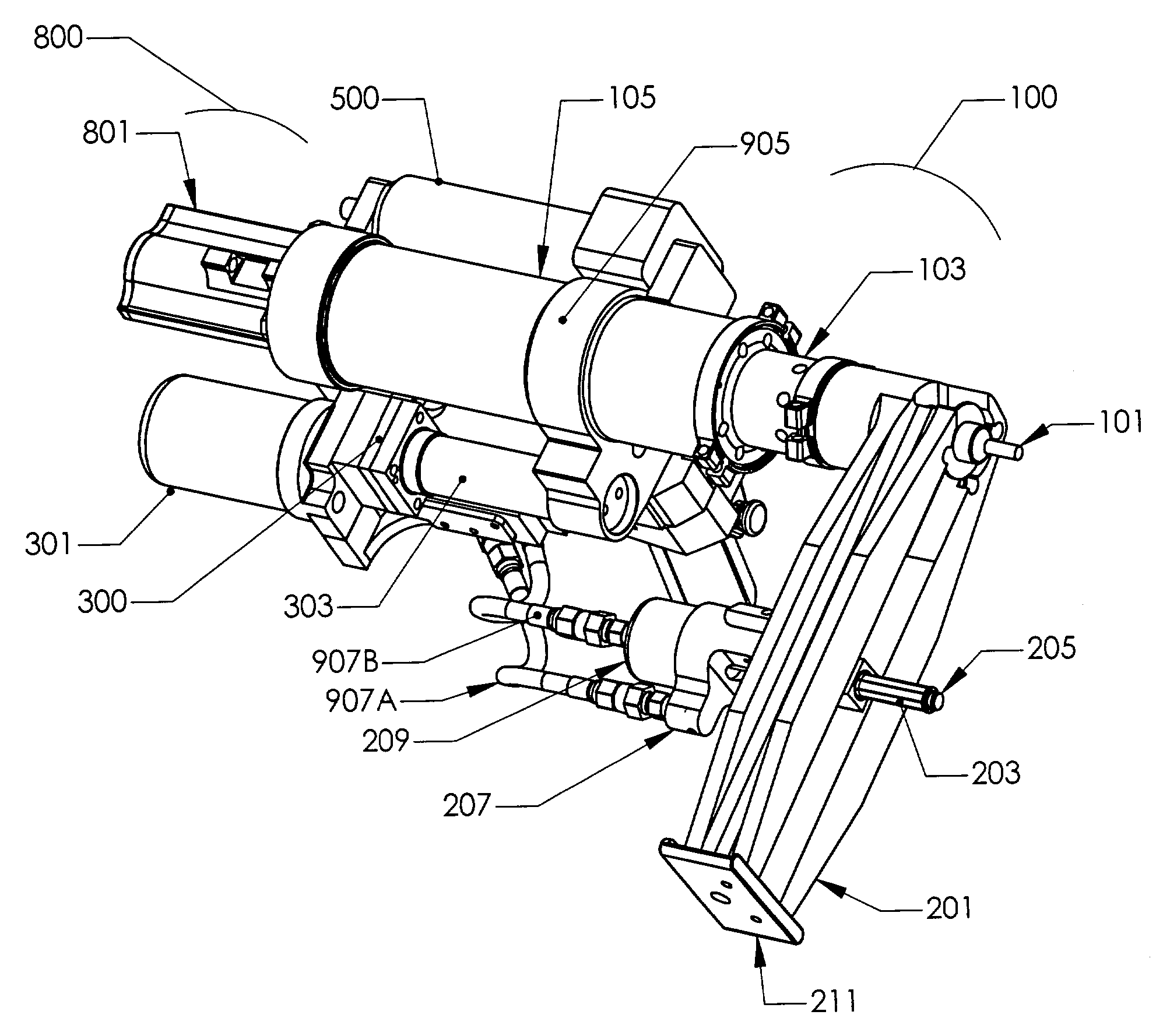
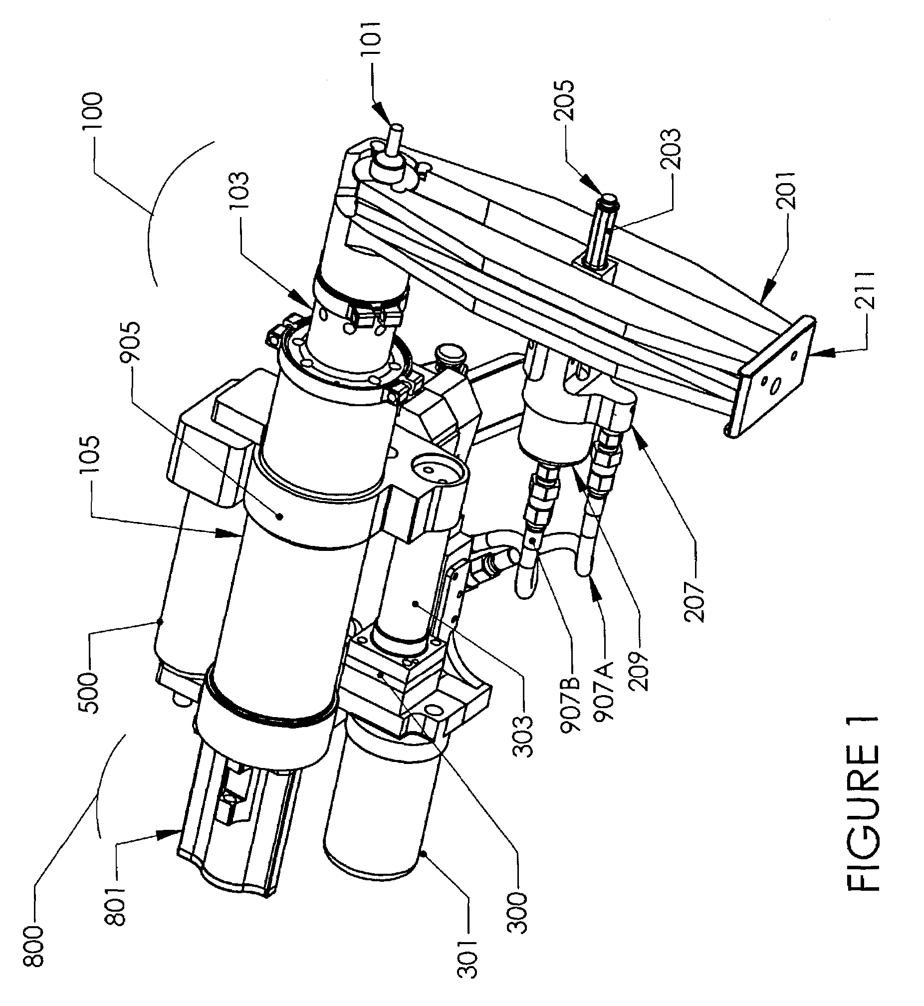
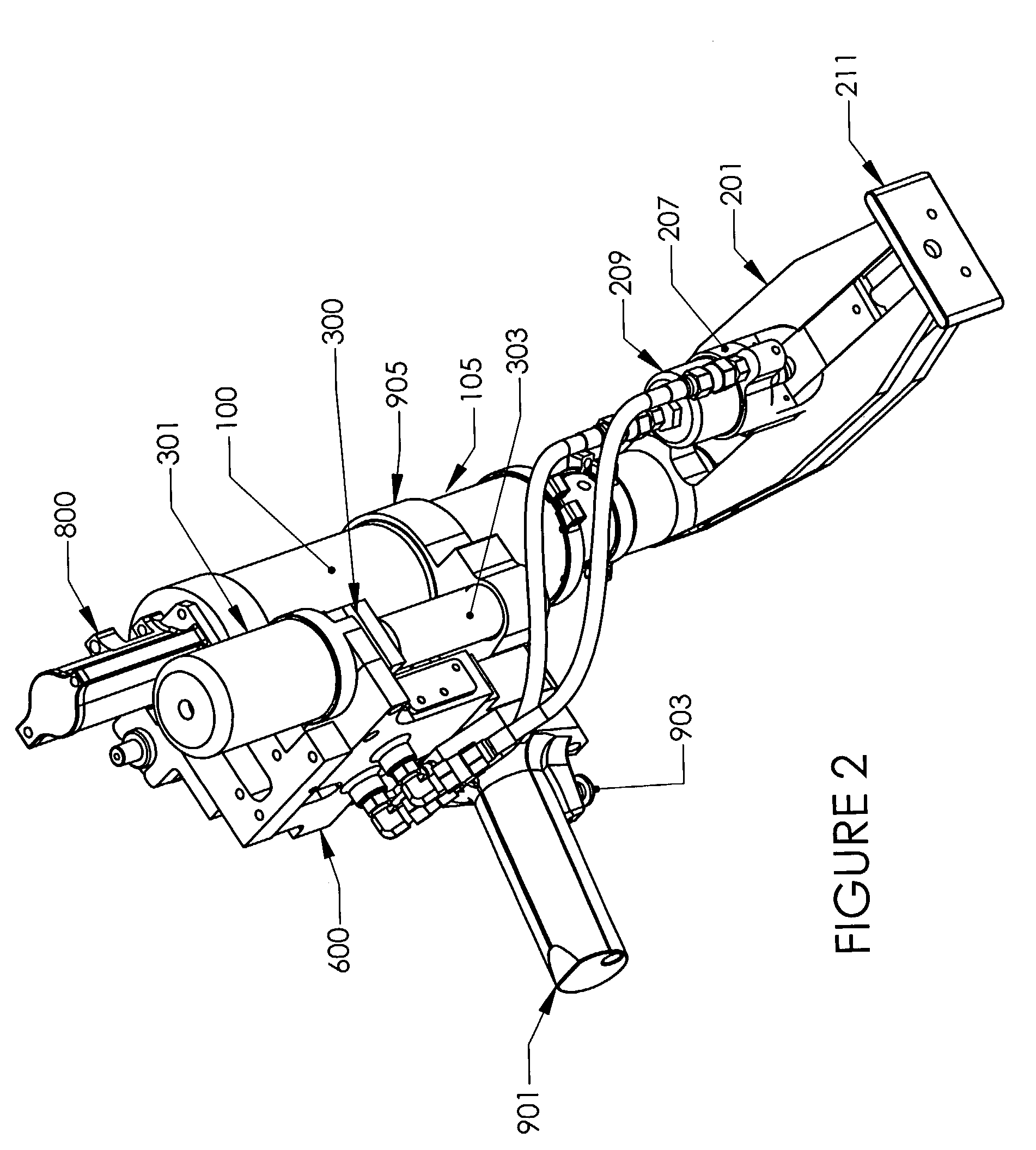
[0039]Referring now to the drawings, and especially to FIGS. 1, 2, and 3 initially, the general configuration of a drill apparatus can be described. One of the main components of the drill of the present invention is a drill spindle assembly generally designated as reference numeral 100. The drill spindle assembly 100 has a main housing 105, and nosepiece 103 extending from the forward end of the main housing 105. The details of the nosepiece 103 and of the drill spindle 100 will be described later in the disclosure, the present discussion identifying only the general configuration of the drill. In any case, the drill nosepiece 103 holds a drill bit 101 which extends from the forward end of the drill nosepiece 103. The drill bit 101 is used to perform work on a hole in the workpiece (not shown in FIGS. 1, 2, and 3). The main housing 105 contains an air motor 107 (best seen in FIG. 4) which serves to rotate the drill bit 101 during operation of the apparatus. A feed assembly generall...


PUM

PropertyMeasurementUnit
Shapeaaaaaaaaaa
Tensionaaaaaaaaaa

Abstract

A portable power drill having an automatic drilling cycle for feeding a rotating tool bit to a workpiece to effect the desired operation. The drill uses a rotary gerotor pump to pump hydraulic fluid used in its system, and pressurized air to operate the hydraulic pump. The drill has a clamping assembly which clamps the unit on a workpiece before the drill bit is advanced toward the workpiece. The drill also has an integral drill spindle-planet carrier area which adds to its operability and reliability.

Description

BACKGROUND OF THE INVENTION[0001]1. Field of the Invention[0002]This invention relates to portable power tools and more specifically, to powered drilling apparatus of the type that executes an automatic drilling cycle consisting of: (1) clamping the drilling apparatus to the workpiece and, in most instances, to a template or jig that positions the drill spindle relative to the workpiece; (2) advancing or feeding a rotating tool bit (e.g., twist drill, countersink, or combined twist drill-countersink) to effect the desired machining operations; (3) withdrawing the tool bit from the machined opening and (4) releasing the clamping mechanism that secures the drilling apparatus to the workpiece.[0003]2. Description of the Prior Art[0004]Pneumatically operated, self-colleting, power feed drill motors of the above-mentioned type are presently utilized in the manufacture of various structural assemblies, being of particular importance in the drilling and countersinking of precision holes du...

Claims


Application Information

Patent Timeline
IPC IPC(8): B23B47/22B23B47/08B23Q5/26
CPCB23Q5/26Y10T408/557Y10S408/702Y10T408/65Y10T408/6757
Inventor SHEMETA, PAUL JOSEPH
Owner WEST COAST INDS
Why Eureka
Try Eureka